

21
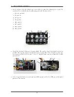
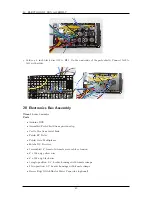
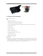
ELECTRONICS BOX INSTALLATION
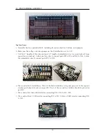
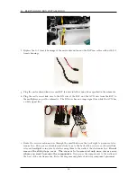
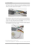
f. Replace the 3
×
1 female housings of the motor shroud fan and the ESC fan cables with with 2
×
1
female housings.
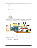
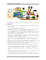
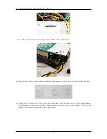
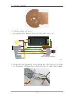
g. Plug the motor shroud fan wires and ESC fan wire into the connections specified in the schematic.
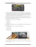
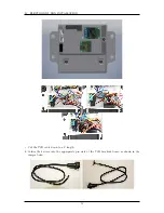
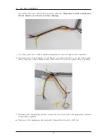
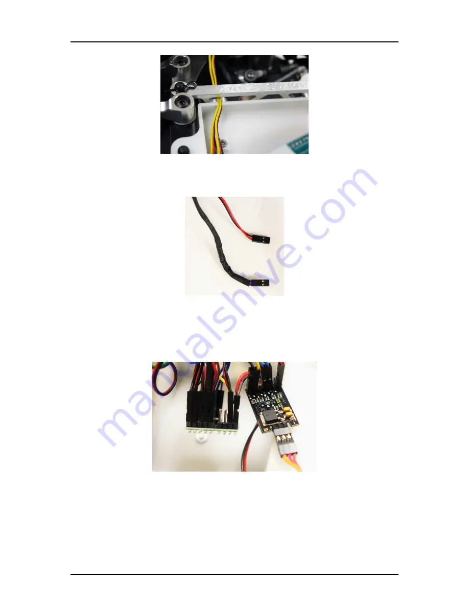
h. Plug the castle serial link wire to the RX wire of the ESC and the AUX wire from the ESC to
the multiplexer as per the schematic. The RX wire has an orange signal line while the AUX has
a white signal line.
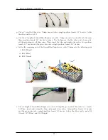
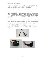
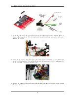
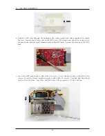
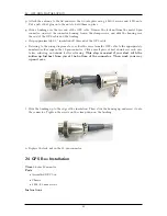
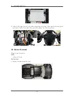
i. Route the receiver antenna wire through the small hole near the back right top corner of elec-
tronics box. Put a piece of double-sided sticky tape to the back of the receiver, castle serial link,
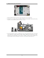
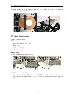
relay and multiplexer in order to start securing them to the walls of the electronics box.
Do not
remove the sticky-tape cover. The cover is to be removed only once you are sure
where you want to secure the components.
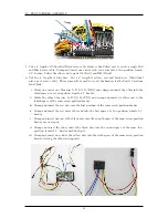
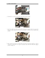
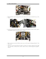
Now secure the components to the walls and
the base of the electronics box. Refer the diagram and photos below for component placement.
50
Summary of Contents for AutoRally
Page 1: ...AutoRally Chassis Instructions Version 1 4 June 2018 Georgia Institute of Technology...
Page 2: ......
Page 79: ...27 APPENDIX A PARTS Futaba FUTM1725 Charger for Futaba 4PV Glitch Capacitor GPS antenna 75...
Page 80: ...27 APPENDIX A PARTS GPS antenna cable GPS box fan Hallogic OH090U Hall Effect sensors 76...
Page 88: ...27 APPENDIX A PARTS 1 M3 4mm screw 27 7 3 GPS Box 8 M3 8mm screws 4 M3 hex nuts 84...
Page 89: ...27 APPENDIX A PARTS 2 M1 4 fan screws 2 M1 4 fan nuts 2 M3 25mm screws 85...
Page 92: ......