

21
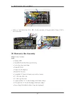
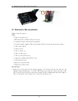
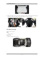
ELECTRONICS BOX INSTALLATION
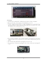
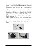
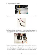
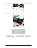
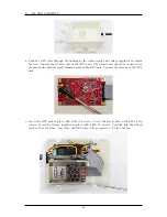
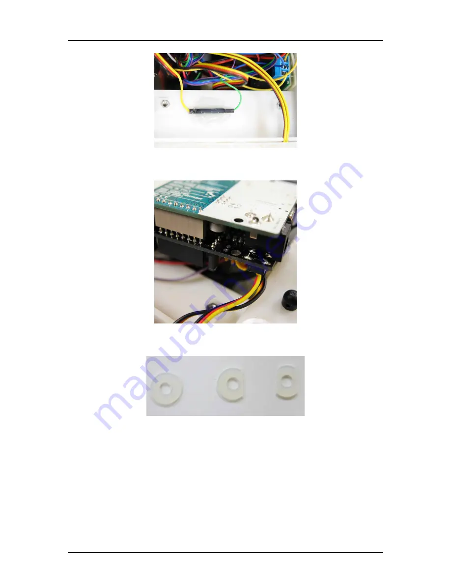
o. Use pliers to flatten the solder tips of the button of the protoboard.
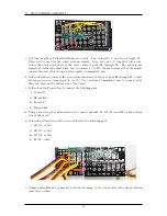
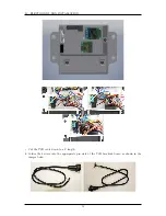
p. Clip-off two of the nylon washers as shown in the images as they do not sit flat on the Arduino.
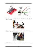
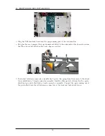
q. Attach the Arduino Due to the electronics box using 3 M3x40 mm screws, 3 M3 nylon washers,
3 M3x18 mm nylon spacers to the 3 nuts epoxied in Step 1; do not over-tighten. Refer to the
image to see which clipped-off washer goes where.
53
Summary of Contents for AutoRally
Page 1: ...AutoRally Chassis Instructions Version 1 4 June 2018 Georgia Institute of Technology...
Page 2: ......
Page 79: ...27 APPENDIX A PARTS Futaba FUTM1725 Charger for Futaba 4PV Glitch Capacitor GPS antenna 75...
Page 80: ...27 APPENDIX A PARTS GPS antenna cable GPS box fan Hallogic OH090U Hall Effect sensors 76...
Page 88: ...27 APPENDIX A PARTS 1 M3 4mm screw 27 7 3 GPS Box 8 M3 8mm screws 4 M3 hex nuts 84...
Page 89: ...27 APPENDIX A PARTS 2 M1 4 fan screws 2 M1 4 fan nuts 2 M3 25mm screws 85...
Page 92: ......


