
21
ELECTRONICS BOX INSTALLATION
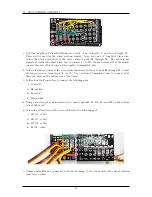
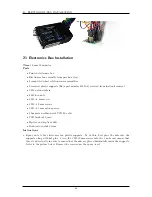
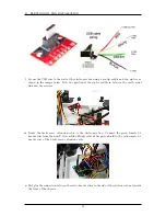
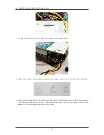
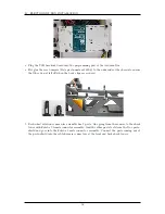
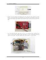
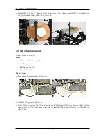
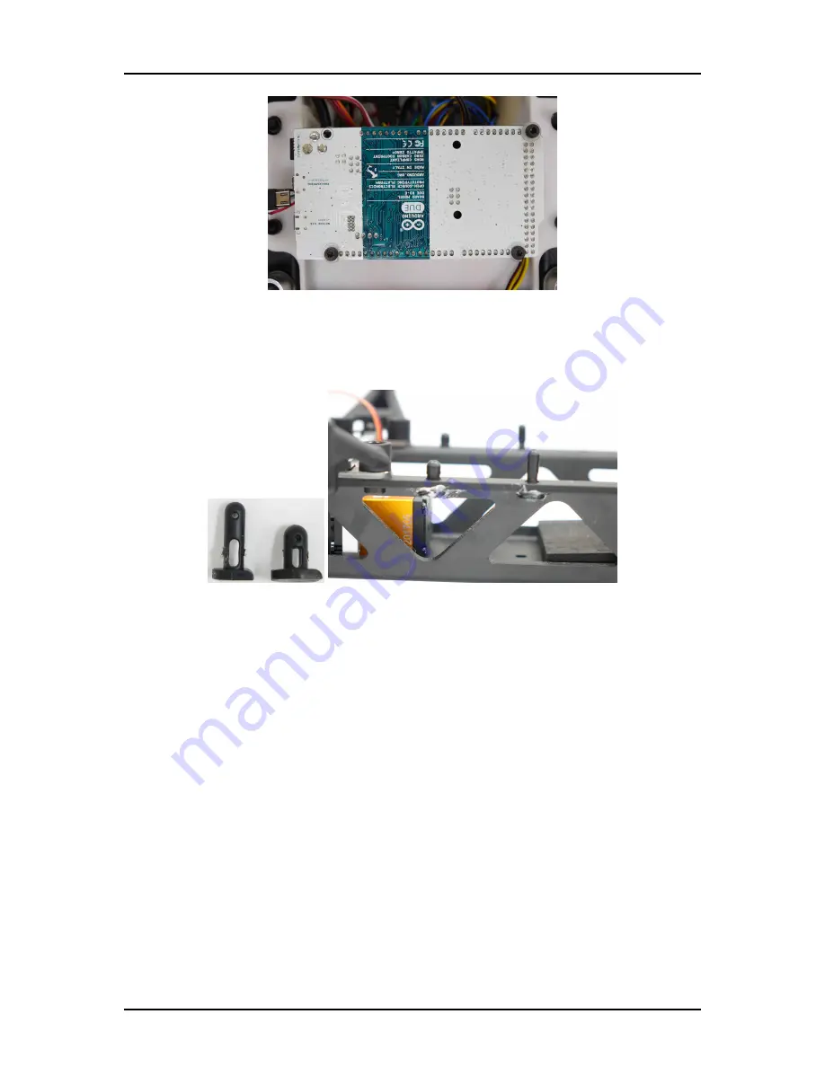
r. Plug the USB breakout board into the programming port of the Arduino Due.
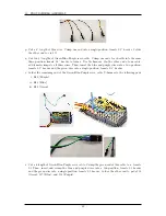
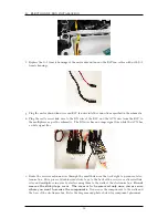
s. Hot glue the rear bumpers (Baja part number 85420-6) to the underside of the chassis to ensure
that they do not fall off when the body clips are secured.
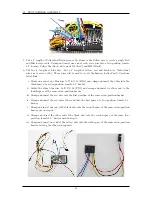
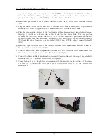
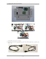
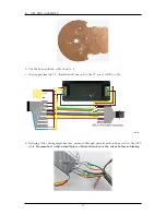
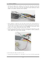
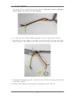
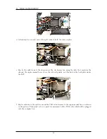
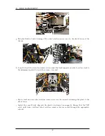
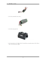
t. Each wheel rotation sensor wire assembly has 2 parts. One going from the sensors to the shock
tower with Futaba J female connector assembly. And,the other part starts from the Due proto-
shield and goes into the Futaba J male connector assembly. Connect the parts coming out of
the proto-shield into the cable harness connectors at the front and back shock towers.
54
Summary of Contents for AutoRally
Page 1: ...AutoRally Chassis Instructions Version 1 4 June 2018 Georgia Institute of Technology...
Page 2: ......
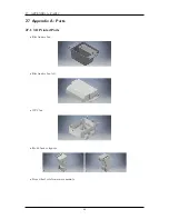
Page 79: ...27 APPENDIX A PARTS Futaba FUTM1725 Charger for Futaba 4PV Glitch Capacitor GPS antenna 75...
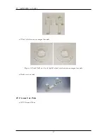
Page 80: ...27 APPENDIX A PARTS GPS antenna cable GPS box fan Hallogic OH090U Hall Effect sensors 76...
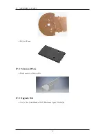
Page 88: ...27 APPENDIX A PARTS 1 M3 4mm screw 27 7 3 GPS Box 8 M3 8mm screws 4 M3 hex nuts 84...
Page 89: ...27 APPENDIX A PARTS 2 M1 4 fan screws 2 M1 4 fan nuts 2 M3 25mm screws 85...
Page 92: ......