
23
GPS BOX ASSEMBLY
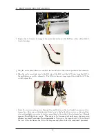
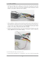
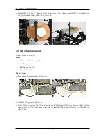
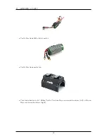
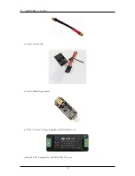
wires in the GPS cable, and tin the leads on the other end.
Remember to slide a small piece
of heat shrink over the wires before soldering.
j. Use a heat gun to heat all heat shrink ensuring that it covers all exposed wire and solder.
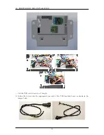
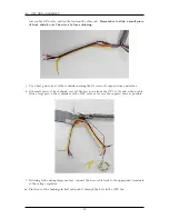
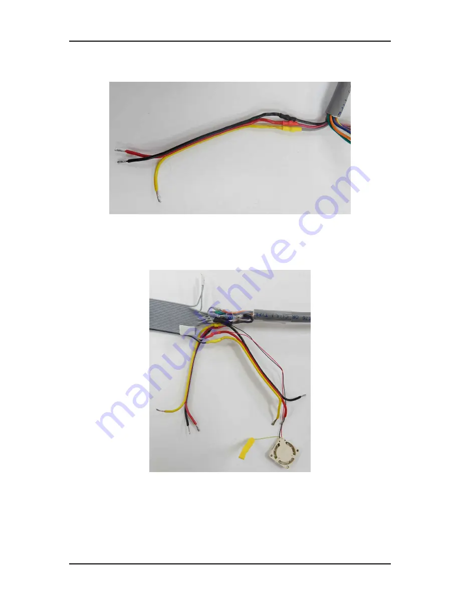
k. Put small pieces of heat shrink over all the free wires from the GPS cable and ribbon cable.
Slide a large piece of heat shrink over the GPS cable as far over the exposed wires as possible.
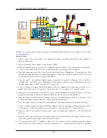
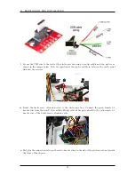
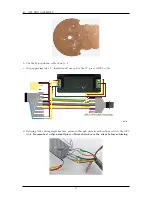
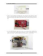
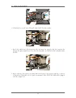
l. Referring to the wiring diagram above, connect the servo cable leads to the appropriate terminals
of the voltage regulator.
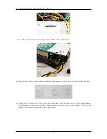
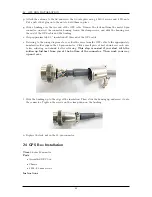
m. Pinch one of the bushings in half and push it through the hole in the GPS box.
59
Summary of Contents for AutoRally
Page 1: ...AutoRally Chassis Instructions Version 1 4 June 2018 Georgia Institute of Technology...
Page 2: ......
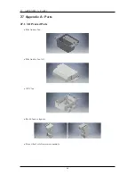
Page 79: ...27 APPENDIX A PARTS Futaba FUTM1725 Charger for Futaba 4PV Glitch Capacitor GPS antenna 75...
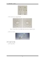
Page 80: ...27 APPENDIX A PARTS GPS antenna cable GPS box fan Hallogic OH090U Hall Effect sensors 76...
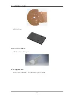
Page 88: ...27 APPENDIX A PARTS 1 M3 4mm screw 27 7 3 GPS Box 8 M3 8mm screws 4 M3 hex nuts 84...
Page 89: ...27 APPENDIX A PARTS 2 M1 4 fan screws 2 M1 4 fan nuts 2 M3 25mm screws 85...
Page 92: ......


