
23
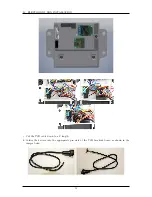
GPS BOX ASSEMBLY
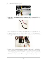
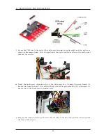
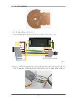
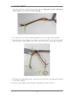
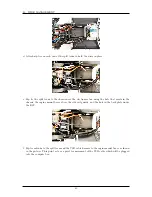
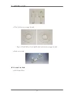
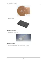
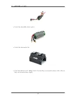
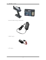
n. Push the GPS cable through the bushing so the ribbon cable and voltage regulator are inside
the box. Connect the ribbon cable to the GPS unit. The colored wire should be connected to
the pin labeled with the small diamond mark on the GPS unit. Connect the antenna to the GPS
unit.
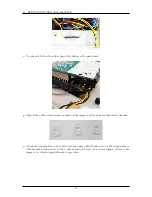
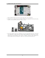
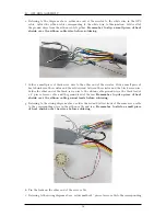
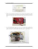
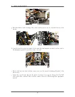
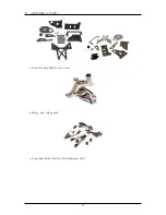
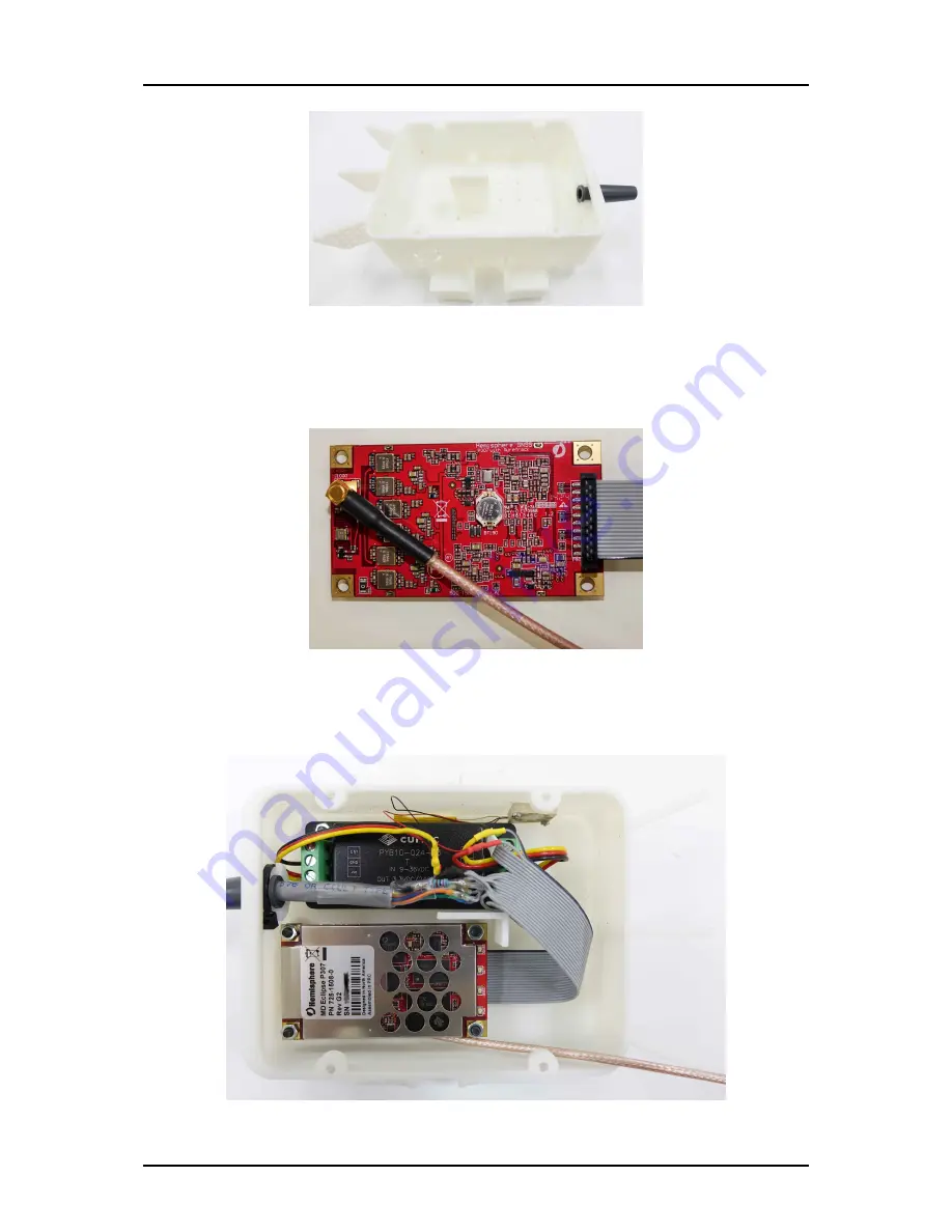
o. Screw the GPS unit in place with 4 M3
×
12 screws. Screw the fan in place with 2 M1.4 fan
screws. Screw the voltage regulator in place with 2 M3
×
12 screws. Carefully fold the ribbon
cable so that all items – fan, cable, and GPS unit, voltage regulator – fit into the box.
60
Summary of Contents for AutoRally
Page 1: ...AutoRally Chassis Instructions Version 1 4 June 2018 Georgia Institute of Technology...
Page 2: ......
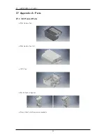
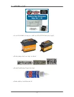
Page 79: ...27 APPENDIX A PARTS Futaba FUTM1725 Charger for Futaba 4PV Glitch Capacitor GPS antenna 75...
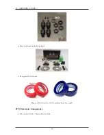
Page 80: ...27 APPENDIX A PARTS GPS antenna cable GPS box fan Hallogic OH090U Hall Effect sensors 76...
Page 88: ...27 APPENDIX A PARTS 1 M3 4mm screw 27 7 3 GPS Box 8 M3 8mm screws 4 M3 hex nuts 84...
Page 89: ...27 APPENDIX A PARTS 2 M1 4 fan screws 2 M1 4 fan nuts 2 M3 25mm screws 85...
Page 92: ......


