12
FRONT AND REAR ROTATION SENSORS
12 Front and Rear Rotation Sensors
Time
1 hours 30 minutes
Parts
•
6 Optek Hallogic OH090U Hall Effect Sensors
•
6 Futaba J female connector assemblies
•
6 11” lengths of servo wire
•
Heat shrink
•
Zip ties
Instructions
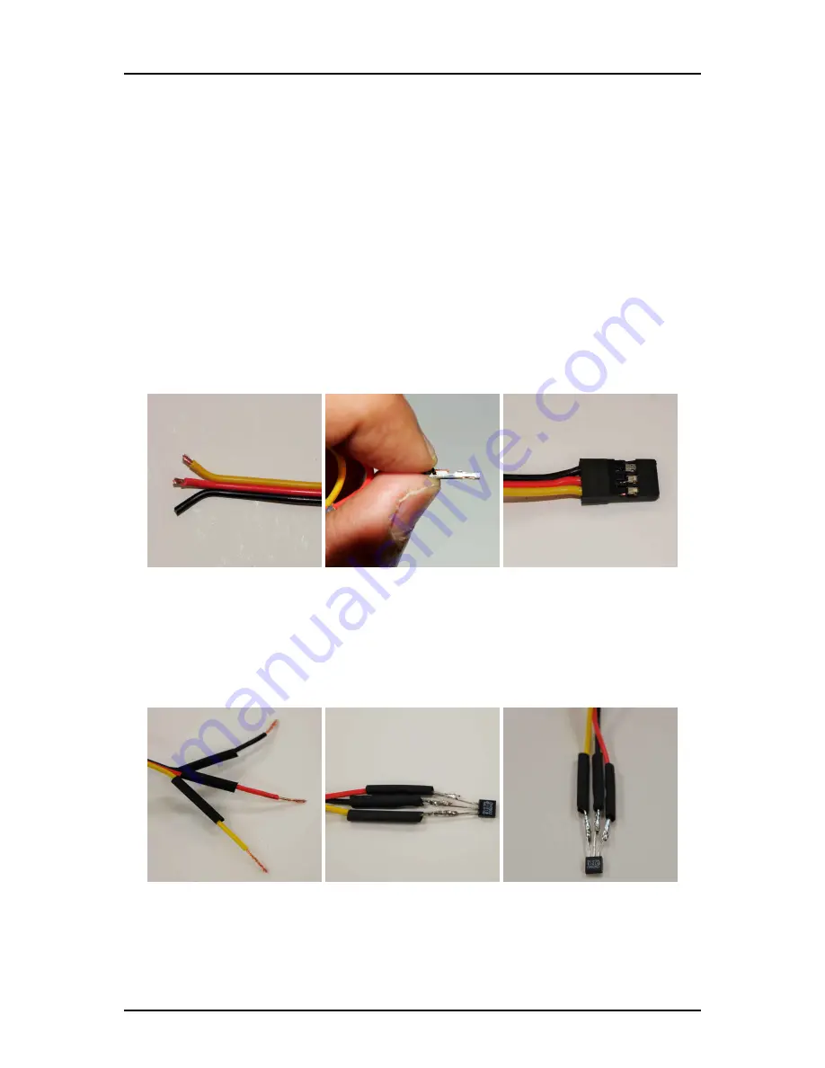
a. Follow this
and the
to learn how to crimp these
connectors.
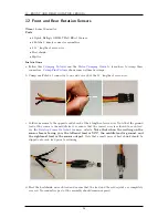
shows some well-made crimps.
b. Crimp one Futaba J connector to one side of each of the 11” lengths of servo wire.
c. Solder one sensor to the opposite end of each of the 6 lengths of servo wire. Note that the ground
lead of the sensor is the middle lead, so ensure that the correct wire is soldered to each lead.
See the
for more details.
Note that when the writing on the
sensor face is facing you, the leftmost lead is VCC, the middle lead is ground, and
the rightmost lead is the sensor output
. Note that a small piece of heat shrink should be
slipped onto each lead prior to soldering.
d. Heat the heatshrink on each lead and ensure that the lead and the solder joint are completely
covered. No conductive part of the assembly should remain exposed.
26
Summary of Contents for AutoRally
Page 1: ...AutoRally Chassis Instructions Version 1 4 June 2018 Georgia Institute of Technology...
Page 2: ......
Page 79: ...27 APPENDIX A PARTS Futaba FUTM1725 Charger for Futaba 4PV Glitch Capacitor GPS antenna 75...
Page 80: ...27 APPENDIX A PARTS GPS antenna cable GPS box fan Hallogic OH090U Hall Effect sensors 76...
Page 88: ...27 APPENDIX A PARTS 1 M3 4mm screw 27 7 3 GPS Box 8 M3 8mm screws 4 M3 hex nuts 84...
Page 89: ...27 APPENDIX A PARTS 2 M1 4 fan screws 2 M1 4 fan nuts 2 M3 25mm screws 85...
Page 92: ......

