23
GPS BOX ASSEMBLY
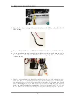
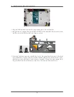
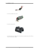
i. Castle Serial Link data is being transmitted (battery voltage, motor speed, ...).
ii. Spin each axle to verify the wheel rotation sensors are mounted properly and plugged into
the correct spot.
iii. Manual and autonomous mode are correctly detected.
iv. Run stop state is correctly detected.
v. Manual throttle and steering commands from the transmitter are sensed correctly.
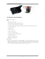
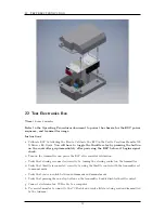
23 GPS Box Assembly
Time
4 hours 0 minutes
Parts
•
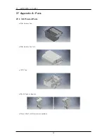
GPS box
•
GPS box lid
•
GPS box tab
•
15” 12-pin GPS cable
•
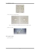
Hemisphere P307 GPS unit
•
GPS antenna cable
•
4 1/4” 6-32 screws for the GPS antenna
•
12” 20-pin ribbon cable
•
12-pin male solder cup connector
•
2 rubber bushings
•
Cui 3.3V isolated voltage regulator
•
10kΩ Resistor
•
1” piece of black servo wire
•
2 4” pieces of servo cable
•
Copper conductive tape
•
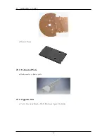
Sunon UF3F3-500 fan
•
2 M1.4 fan screws
•
2 M1.4 fan nuts
•
4 M3
×
8 mm screws
•
6 M3
×
12 mm screws
•
10 M3 nuts
Instructions
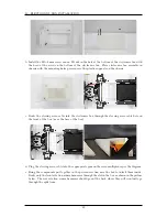
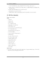
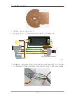
a. Cover the top of the GPS box lid with a single layer of copper conductive tape. Cut out the
larger holes and poke through the smaller holes.
56
Summary of Contents for AutoRally
Page 1: ...AutoRally Chassis Instructions Version 1 4 June 2018 Georgia Institute of Technology...
Page 2: ......
Page 79: ...27 APPENDIX A PARTS Futaba FUTM1725 Charger for Futaba 4PV Glitch Capacitor GPS antenna 75...
Page 80: ...27 APPENDIX A PARTS GPS antenna cable GPS box fan Hallogic OH090U Hall Effect sensors 76...
Page 88: ...27 APPENDIX A PARTS 1 M3 4mm screw 27 7 3 GPS Box 8 M3 8mm screws 4 M3 hex nuts 84...
Page 89: ...27 APPENDIX A PARTS 2 M1 4 fan screws 2 M1 4 fan nuts 2 M3 25mm screws 85...
Page 92: ......

