24
GPS BOX INSTALLATION
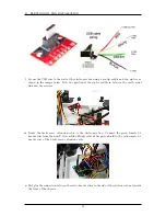
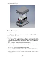
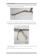
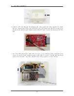
p. Attach the antenna to the lid and screw the lid into place using 4 M3
×
8 screws and 4 M3 nuts.
Put a dab of hot glue onto the nuts to hold them in place.
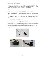
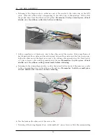
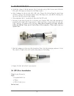
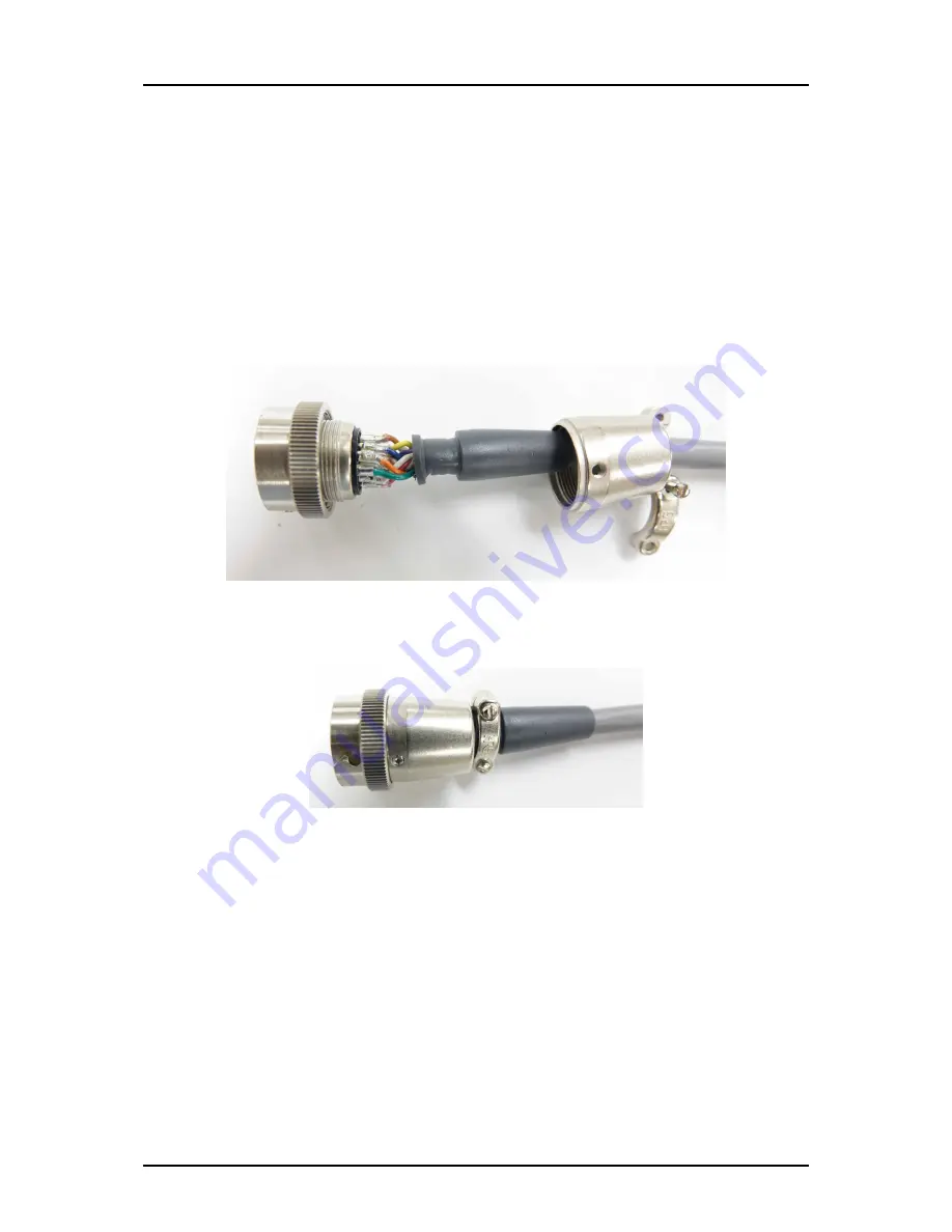
q. Slide a bushing over the free end of the GPS cable. Remove the lock nut from the male 12-pin
connector, unscrew the connector housing, loosen the clamp screws, and slide the housing over
the end of the GPS cable and the bushing.
r. Strip approximately 0.5” insulation off this end of the GPS cable.
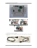
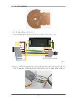
s. Referring to the wiring diagram above, solder the wires from the GPS cable to the appropriately
numbered solder cups in the 12-pin connector. Slide a small piece of heat shrink over each wire
before soldering, and shrink it after soldering.
This step is easiest if you start with the
soldercup furthest from you at the bottom of the connector. Then work your way
up and over.
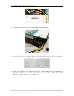
t. Slide the bushing up to the edge of the insulation. Then, slide the housing up and screw it onto
the connector. Tighten the screws on the clamp down on the bushing.
u. Replace the lock nut in the 12-pin connector.
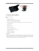
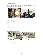
24 GPS Box Installation
Time
0 hours 20 minutes
Parts
•
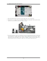
Assembled GPS box
•
Chassis
•
4 M4
×
20 mm screws
Instructions
61
Summary of Contents for AutoRally
Page 1: ...AutoRally Chassis Instructions Version 1 4 June 2018 Georgia Institute of Technology...
Page 2: ......
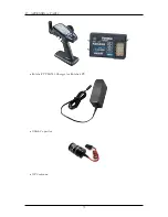
Page 79: ...27 APPENDIX A PARTS Futaba FUTM1725 Charger for Futaba 4PV Glitch Capacitor GPS antenna 75...
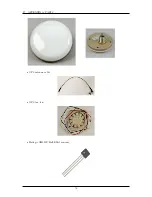
Page 80: ...27 APPENDIX A PARTS GPS antenna cable GPS box fan Hallogic OH090U Hall Effect sensors 76...
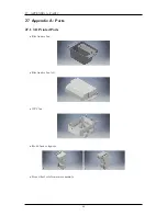
Page 88: ...27 APPENDIX A PARTS 1 M3 4mm screw 27 7 3 GPS Box 8 M3 8mm screws 4 M3 hex nuts 84...
Page 89: ...27 APPENDIX A PARTS 2 M1 4 fan screws 2 M1 4 fan nuts 2 M3 25mm screws 85...
Page 92: ......

