User Manual - P series
10
www.georgin.com
2. Mounting
!
Avoid mounting on a vibrating wall. This may result in a premature electrical malfunction.
It is especially when approaching the changeover thresholds that our devices are particularly sensitive to
certain vibration frequencies.
If no other mounting is possible, we recommend the use of elastic suspensions for any use on a vibrating
wall, especially in the case of a slow evolution of the pressure or temperature.
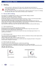
2.1. Pressure switch mounting
The instruments are equipped with a 1/2’’ GM or 1/4’’ GF (to ISO 228-1) fitting as standard.
Other fittings on request (NPT connection to ASA B2-1).
Optional connection by soldered tab (see fc-a3500-fren).
To make the connections, use the appropriate spanners for the fittings, and never use the housing to tighten.
Recommended tightening torque for the pressure fitting: 50 N∙m for the 1/2’’ GM.
Check that the pressure inlet tubes are not applying any mechanical load to the fitting and the housing.
Observe the environmental and fluid-related conditions corresponding to the characteristics of the instruments.
Provide tubing or a capillary to avoid any overheating through conduction.
Never exceed the maximum pressure of the instrument indicated on the label on the side of the housing.
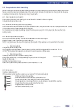
2.1.1. Monitoring liquid pressure :
The pressure switch must be installed under the pressure fittings.
The pipework must be installed in a way that prevents any accumulation of gas in the pressure switch.
The installation of a gas collection tank is recommended.
The pipes connecting the process to the pressure switch must have a descending slope of at least 1/10 to
prevent gas accumulation.
2.1.2. Monitoring gas pressure :
The pressure switch must be installed above the pipes to prevent condensation in the connection pipes and the
pressure switch measurement chambers.
If the gas temperature is high, a cooler or a siphon may be used.
The pipes connecting the process to the pressure switch must have a rising slope of at least 1/10 to prevent
the accumulation of liquid or condensates.
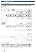
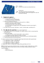
2.1.3. Monitoring the vapour pressure :
The pressure switch may be installed laterally or under the pressure fittings.
A condensate vessel must be installed between the pressure switch and the pressure fitting.
The pipe or pigtail siphon (see fc-a3000-fren) connecting the condensate vessel to the pressure switch must be
filled with water beforehand.
A bleeder valve must be installed.
Lateral installation
Installation under the pressure fitting


