User Manual - P series
9
www.georgin.com
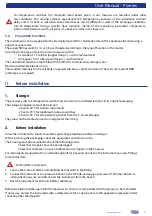
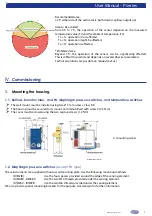
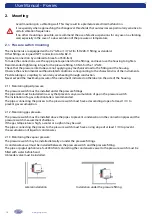
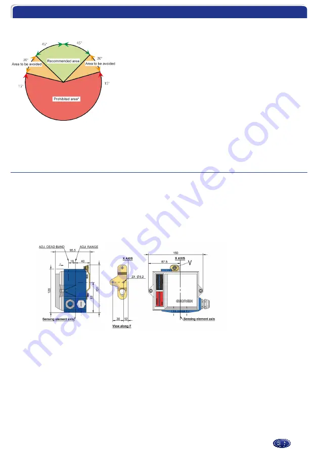
Recommended area:
±45° either side of the vertical axis, bulb down (capillary output up).
Area to be avoided:
from 45° to 75°, the operation of the sensor depends on the measured
temperature value (Ts) and the ambient temperature (Ta):
Ta > Ts: operation is not affected,
Ta < Ts: operation might be affected,
Ta = Ts: operation is affected.
*Prohibited area
Beyond 75°, the operation of the sensor can be significantly affected.
This is difficult to predict and depends on several physical parameters.
Technical solutions are possible on request (ask us).
IV.
Commissioning
1. Mounting the housing
1.1. Bellows, Bourdon tube, and PA diaphragm pressure switches, and temperature switches
¾
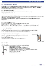
The wall mount must be installed using two Ø 5 mm screws, Class 8.8
¾
The housing must be secured to its mount and immobilised with screw V (2.5 N∙m)
¾
The cover must be closed using the two captive screws (1.2 Nm).
Dimensions in mm.
V: mounting screw
1.2. Diaphragm pressure switches
(except PA type)
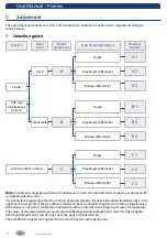
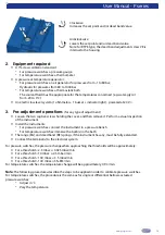
These instruments are supplied without a wall mounting plate. Use the following mounting methods:
(D)ML(B):
Use the four spacers provided around the edge of the sensing element.
(D)MABV - DMKBV:
Use the two M10 threads provided under the sensing element.
(D)MJBV - (D)MPB:
Use the two M6 threads provided under the sensing element.
We also provide special mounting brackets for the purpose. Ask Georgin for further information.


