AKULA 9000B USER MANUAL
/ SECTION 3
REV:EN05130513-03
Copyright 2006-2015 © Geoscanners AB
22
3.4.4
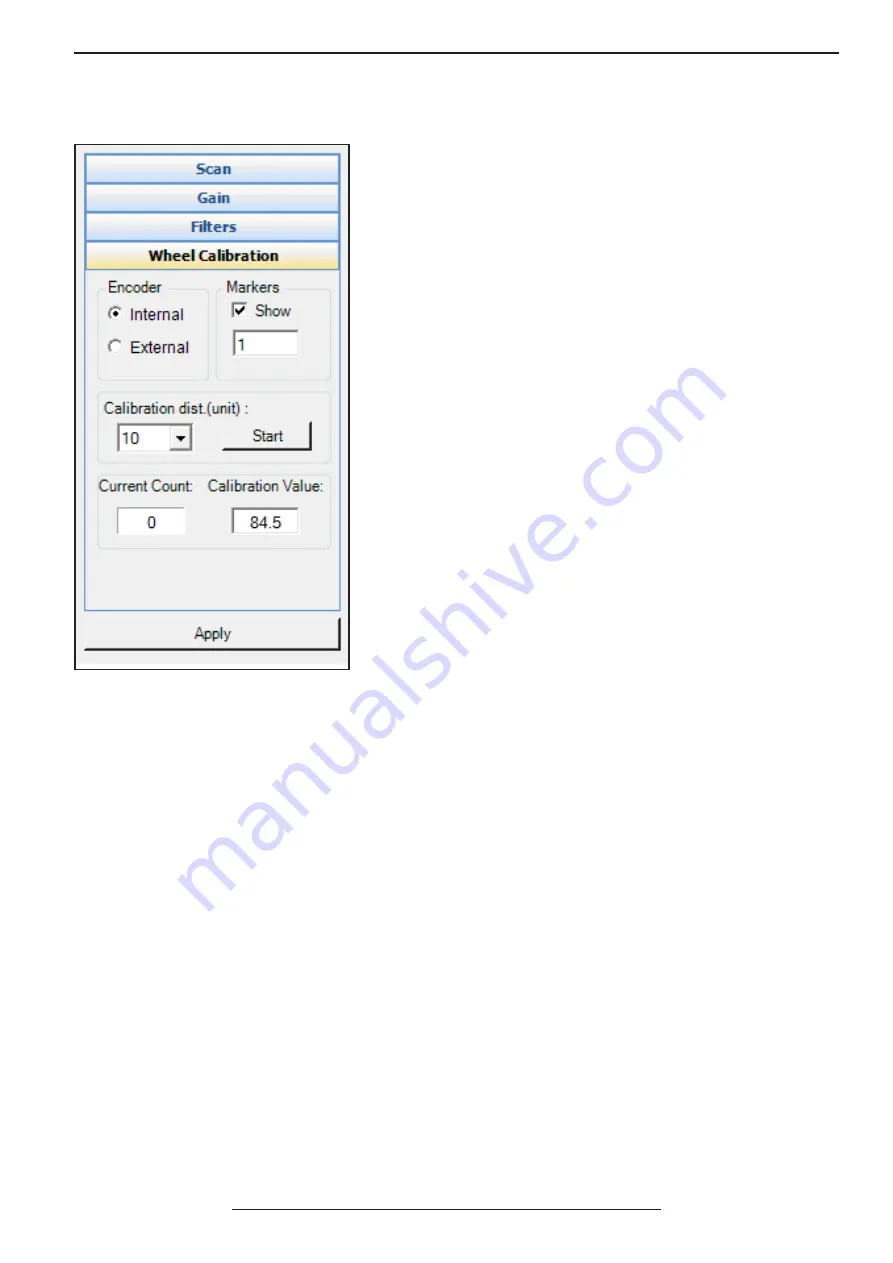
Wheel Calibration Box
The wheel calibration box is where we have all the controls to
attach survey wheel encoders to your control unit. It is mandatory
to do a wheel calibration every time you connect a new encoding
unit to your ground penetrating radar. It is also highly recommended
to perform a calibration of your survey wheel regularly.
The encoder section allows us to select the port where the survey
wheel encoder is going to be attached. Please note that the other
port will be completely ignored. If the “internal” radio button is
selected then your survey wheel encoder must be attached to the
radar directly using the supplied survey wheel cable for U-Explorer
units or to use one of the approved survey wheel encoders available
from Geoscanners AB. The “external” radio button selects the input
on your antenna and the survey wheel data is then coming via the
control cable supplied with your unit.
The markers section is where we specify if we need to put markers
in the data based on the distance the unit has gone. The check box
“show” will make these markers visible and the field below will set
the amount of units the unit has to go between the markers. It is
worth saying that this amount of units is dependent on the global
settings and if you have a metric system in meters then it will reflect
the amount of meters between the markers. If however, you have
selected the imperial measurement system in feet then the amount
selected reflects the amount of feet between the markers.
The same principle applies to the calibration distance in the
calibration section. The calibration section sets the amount of units
you will use to calibrate your survey wheel encoder.
The drop down menu has a preselection of most common values: 5, 10, 15 etc. This doesn’t mean that you cannot
type in yourself any other value. When you have selected the calibration distance put your survey wheel at the
start of the calibration distance track, press the button “start” and move your cart/wheel forward until you reach
the end of the track. All this time the digits in the field “current count” should be changing indicating that the
survey wheel is actually working and the distance information is coming to your unit. When you have reached the
end of the track press the “stop” button, which is the same that was “start” previously. The new calibration value
now appears in the calibration value field.
If you know the calibration value for your particular survey wheel encoder then you don’t have to necessarily do
the calibration. You can just type the calibration value in the calibration value field and GAS™ will accept it for all
distance calculations.
The sign in the calibration value is assigned so GAS™ recognizes properly the direction of the movement. This
doesn’t mean however, that the minus sign is always backwards and plus forward. In our units we put always
the survey wheel encoders in such a way that the positive values are forward, but it doesn’t mean GAS™ will give
errors if the sign is reversed. As long as the calibration has been performed the rest is taken care by the control
software.
It is important to understand that the calibration value your survey wheel provides is the maximum amount of
traces you will be able to select for the distance unit of your choice. This amount of traces per unit of distance
defines the horizontal resolution your unit will achieve. In some cases this is not that important, while in others
it is crucial. A low resolution will make the recorded hyperbolas look shorter and therefore make more difficult
the interpretation of your files at a later time. The amount of traces per distance unit is set in the “scan box” as
described above.


