GS_GXR_GPS_User_Manual_V03.doc / 22.06.2010
GeoSIG Ltd
GPS User Manual
Page 3
2.2. Mating Connector at the Instrument Side
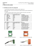
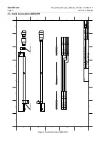
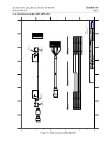
For connecting the GXR-GPS to an Instrument, a mating connector must be used. This connector is
provided with the Instrument.
With a GSR-xx, the connector must be connected to the OPTION connector of the instrument, if not
otherwise specified.
With a CR-5P, the connector must be connected to the SYN in connector of the instrument.
Table 3. Electrical connections of the GXR-GPS input connector of an instrument
Pin
Signal
Standard Cable Colors
Comment
1
GSR_G_TXD
White
Transmit signal of GSR
2
GSR_G_RXD
Brown
Reception signal of GSR
3 N/A
N/A
Not
connected
4 N/A
N/A
Not
connected
5
GSR_G_1PPS
Green
1 PPS signal from GPS
6
GSR_G_12V
Yellow
12V power from instrument
7
GSR_G_GND
Grey
Ground from instrument
Table 4. Electrical connections of the GXR-GPS-485 input connector of an instrument
Pin
Signal
Standard Cable Colors
Comment
1 N/A
N/A
Not
connected
2 S
White
Transmit signal of CR-5P
3 N/A
N/A
Not
connected
4
SYNCI_RX-
Brown
Reception signal of GSR
5
GPS_1PPS
Green
1 PPS signal from GPS
6
V_EXT_GPS
Yellow
12V power from instrument
7
GND_EXT
Grey
Ground from instrument
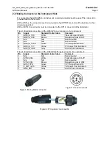
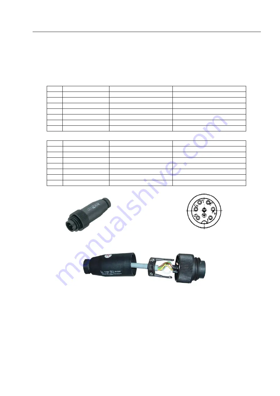
Figure 6. Mating Binder connector
Figure 7. Connector pin out
Figure 8. Wiring inside the connector


