GSB User Manual
GSB User Manual (593-01940-01 Rev C)
release date: TBD
Page 23 of 27
calculated at each sample to construct a residual data set. The RMS of the
residual data is calculated. The impulse comparison result is
100*(residual RMS)/(reference RMS) .
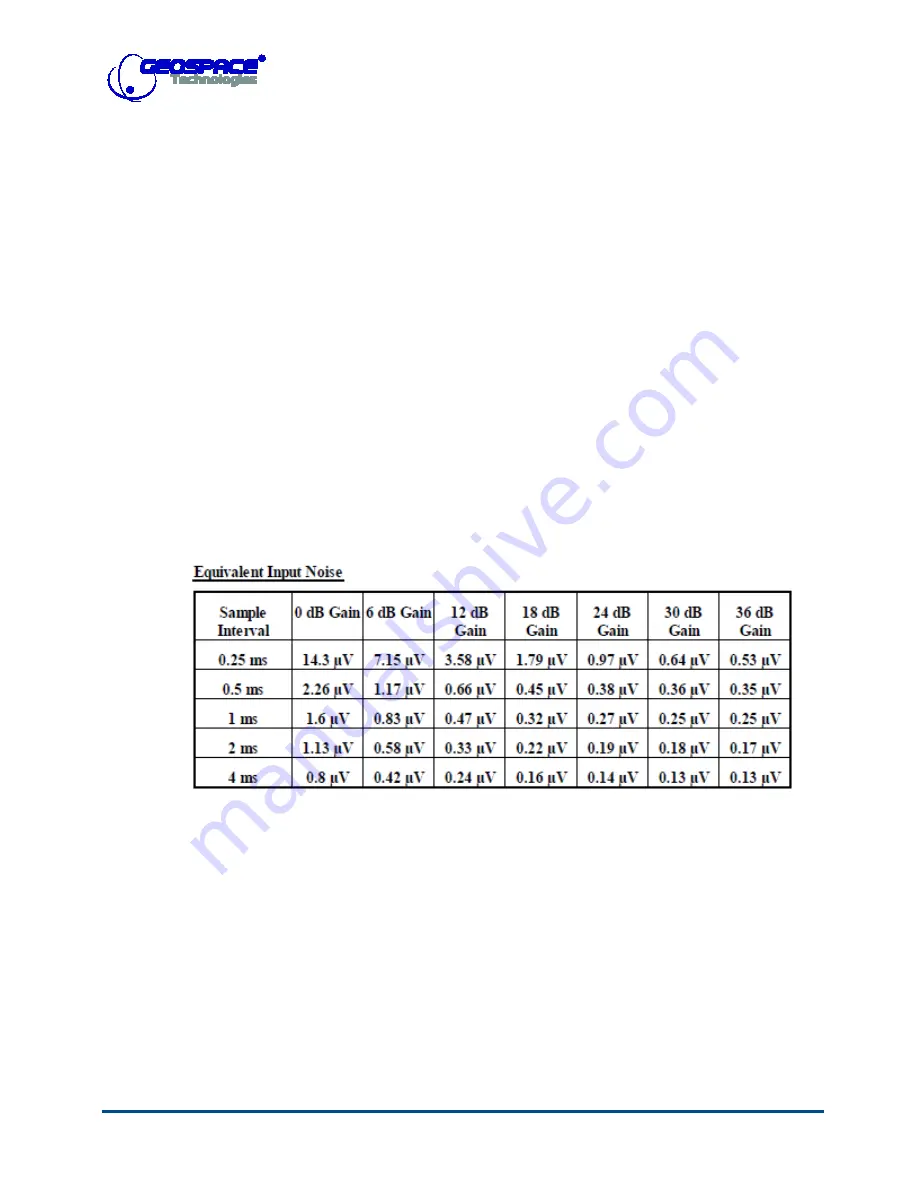
Noise (Equivalent Input Noise)
: This test reports the equivalent input
noise and DC offset values, in micro-volts and nano-volts respectively, of
the pre-amplifier for a specified gain.
The input switches are set to connect to the internal resistors and the test
oscillator is turned off. A record is acquired and the DC offset value is
computed by finding the root mean square (RMS) value of the channel
samples. The DC offset value is removed from the data samples before
computing the RMS value to get the equivalent input noise. Test
specifications are in Table 4.
Table 4: GSB Noise Instrument Test
Impedance
: The input switches are connected to the test oscillator. A
sinusoidal signal of 15.625 Hz is generated at 90% of full amplitude to
give a reference measurement of 2048 samples. A second measurement is
made using the test oscillator to drive the sensor, and the generated
voltage is measured and used to calculate the sensor impedance.
Crossfeed
: This test is implemented only in GSB-3. It measures the
Crossfeed from adjacent channels and reports the results in decibels (dB
Vrms). The test requires a record for each channel. For each record, one
channel’s input switches are at test oscillator position while the other


