GSB User Manual
GSB User Manual (593-01940-01 Rev C)
release date: TBD
Page 24 of 27
channel’s input switches are set to the shunt resistor position. The active
channel is driven with a 31.25Hz sinusoidal signal at full scale, and the
induced Crossfeed voltage on the other channels is measured. The
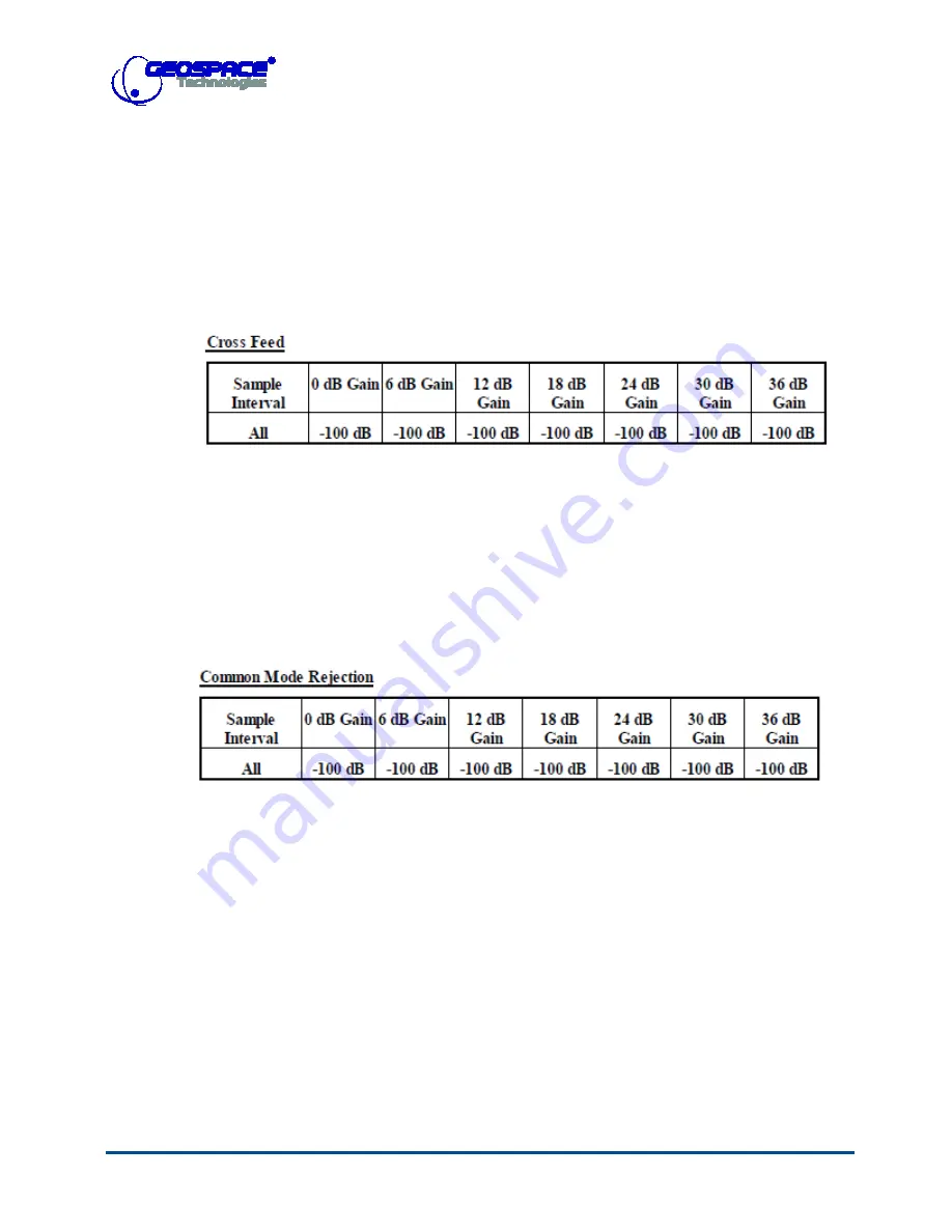
measured Crossfeed voltages are displayed in dBVrms. This test can run
at any gain. Test specifications are in Table 5.
Table 5: GSB-3 Crossfeed Instrument Test
CMRR
: In this test, the input switches are connected to the test
oscillator position. The test oscillator is set to generate a common mode
signal of 31.25 Hz sinusoidal wave at 55% of full amplitude. A data
record is acquired for analysis. The dB Vrms value is computed for each
channel. Parameter specifications are in Table 6.
Table 6: GSB CMRR Instrument Test
5.2 – Sensor test
The GSBs automatically perform sensor tests when they are deployed or any time
programmed by the user during the day or by QC device command.
The sensor tests are
•
Sensor Impedance
: This measures the impedance of the internal
sensor(s). Failures on this test are related to sticking sensors, resonance,
frequency, sensitivity, damping, or distortion geophone failures, and
mainly bad planted geophones (higher tilt than allowed). To perform the
impedance test, the test signal generator provides a sine wave of known
amplitude and frequency selected by the user to all channels and


