10
General Installation Information cont.
air handler TXV should be adjusted initially per TXV Superheat
Adjustments table. Check sub-cooling and superheat, refrigerant
charge and TXV may require further adjustment.
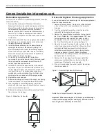
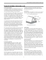
TXV Superheat Adjustment Procedure (see figure 4)
TXV’s may require adjustment for a specific application.
1. Remove the seal cap from the bottom of the valve.
2. Turn the adjustment screw counterclockwise to increase
superheat and clockwise to decrease superheat.
One complete 360° turn changes the superheat
approximately 3-4°F. You may need to allow as much as
30 minutes after the adjustment is made for the system
to
stabilize.
3. Once the proper superheat setting has been achieved
replace and tighten the seal cap.
Warning – There are 8 total (360°) turns on the superheat
adjustment stem from wide open to fully closed. When adjusting
the superheat stem counterclockwise (superheat increase) and the
stop is reached, any further counterclockwise turning adjustment
will damage the valve.
NOTE:
The air handler is factory supplied with a holding charge of
dry nitrogen.
Charging the System
Refer to the unit Installation Manual for charging the system,
checking sub-cooling/superheat and unit operating parameters.
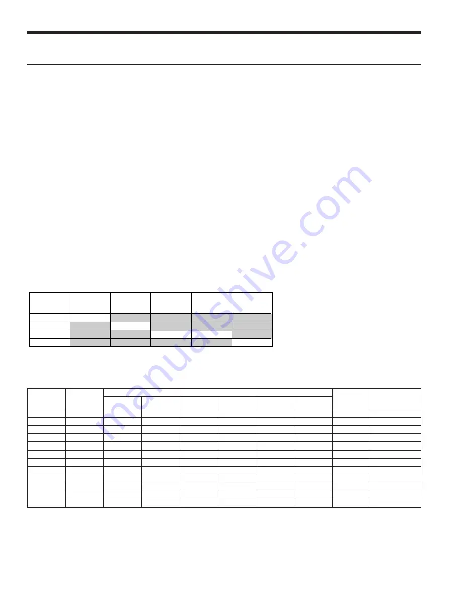
Refer to the Refrigerant Line Sizing table for initial refrigerant
charge amounts used with the compression section.
TXV Superheat Adjustments
ASTON SERIES AIR HANDLER INSTALLATION MANUAL
Part
Number
GAH022,
GAH026,
GAH030
GAH036
GAH042
GAH048
GAH060
33P609-01
factory set
33P609-03
factory set
33P609-05
factory set open 2 turns
33P609-06
open 2 turns
Note: When installing these air handlers, follow the table
for initial txv setting.
Check sub-cooling and superheat to verify final setting.
Unit
Size
Air
Handler
20 feet
40 feet
60 feet
Factory
Charge (oz.)
*Charge Amount
with GAH Air
Handler (oz.)
Suction
Liquid
Suction
Liquid
Suction
Liquid
022
GAH022
5/8” OD
3/8” OD
5/8” OD
3/8” OD
3/4” OD
3/8” OD
56
78
030
GAH030
5/8” OD
3/8” OD
3/4” OD
3/8” OD
3/4” OD
3/8” OD
56
78
036
GAH036
5/8” OD
3/8” OD
3/4” OD
3/8” OD
3/4” OD
1/2” OD
56
86
042
GAH042
3/4” OD
3/8” OD
3/4” OD
3/8” OD
7/8” OD
1/2” OD
74
99
048
GAH048
3/4” OD
3/8” OD
7/8” OD
3/8” OD
7/8” OD
1/2” OD
90
115
060
GAH060
7/8” OD
1/2” OD
7/8” OD
1/2” OD
1-1/8” OD
1/2” OD
92
112
070
GAH060
7/8” OD
1/2” OD
7/8” OD
1/2” OD
1-1/8” OD
1/2” OD
108
132
026
GAH026
5/8” OD
3/8” OD
3/4” OD
3/8” OD
3/4” OD
1/2” OD
52
74
038
GAH036
3/4” OD
3/8” OD
3/4” OD
3/8” OD
3/4” OD
1/2” OD
56
86
049
GAH048
3/4” OD
3/8” OD
7/8” OD
3/8” OD
7/8” OD
1/2” OD
90
115
064
GAH060
7/8” OD
1/2” OD
7/8” OD
1/2” OD
1-1/8” OD
1/2” OD
92
112
072
GAH060
7/8” OD
1/2” OD
7/8” OD
1/2” OD
1-1/8” OD
1/2” OD
104
132
4/6/10
Refrigerant Line Sizing
NOTES:
* The "Charge Amount with GAH Air Handler" column is based on the charge amount for a GAH Air Compressor Section/Split.
Additional charge will have to be added accordingly for line set length.
After Charge is added adjustments can be made to get appropriate subcooling and superheat.
Additional charge for R-410A is 0.50 oz. per ft. for 3/8 in. and 1.0 oz. per ft. for 1/2 in. tube.
Longer line sets will significantly reduce capacity and efficiency of the system as well as adversely effect the system reliability due to poor oil return.


