28
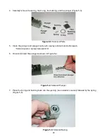
4. Carefully remove the spring, the O-ring, the bushing, and the plunger (Figure 5-3).
Figure 5-3
: Solenoid Parts
5. Clean the plunger and plunger cavity with a spray lubricant and cotton swab.
*Silicon based or aerosol lubricant OK.
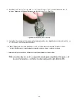
6. Orient and insert the plunger as shown in Figure 5-4.
Figure 5-4
: Solenoid Plunger
7. Place the O-ring and bushing back into the opening (no orientation needed) followed by the spring
(Figure 5-5).
Figure 5-5:
Solenoid Spring
Summary of Contents for Solar Sipper
Page 1: ...Rev 10 12 2017 Part 16550176 Geotech Sipper Installation and Operation Manual...
Page 2: ...i...
Page 16: ...13 Figure 2 5 Example of Tankfull Probe...
Page 23: ...20 Figure 3 1 Flowchart of User Interface Label...
Page 24: ...21 Figure 3 2 Example of Solar Sipper front panel...
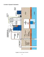
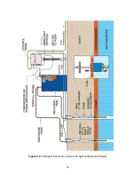
Page 38: ...35 Section 8 System Schematics Figure 8 1 Solar Sipper Schematic...
Page 39: ...36 Figure 8 2 AC Sipper Schematic shown with optional Desiccant Dryers...
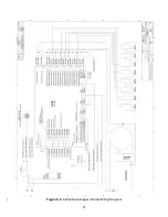
Page 40: ...37 Figure 8 3 8 Well Solar Sipper Internal Wiring Diagram...
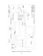
Page 41: ...38 Figure 8 4 3 Well Solar Sipper Internal Wiring Diagram...
Page 45: ...42 Notes...

