33
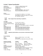
Section 7: System Specifications
Applications
2" (5.8 cm) or larger recovery wells
Recovery Rate
.2 gallons (.750 ml) per cycle
Max. Operating Depth
180
’ (54.86 m)
Max. Pressure
100 PSIG (7 bar)
Max. Vacuum
20" (50 cm) Hg @ MSL (mean sea level)
Oil/Water Separation
Oleophilic/hydrophobic mesh screen
Power
Power Maximums
(AC Sipper) 87 to 240VAC, 2.7 to 1 Amp(s)
(Solar Sipper) 12-15VDC input @ up to 14.5 Amps
90 ~240 Watts continuous
Controller
Operating Temperature
0° to 40° C (32° to 104º F)
Storage Temperature Range
-29° to 66° C (-20º to 150º F)
Humidity
90% non-condensing (max)
Size
10" D x 18" T x 16
” W (25cm D x 46cm T x 40.5cm W)
Rating
NEMA 3R
Approximate Weight
35 lbs (16 kg) (single channel AC Sipper)
Approximate Weight
34 lbs (15 kg) (single channel Solar Sipper)
Approximate Weight
51 lbs (23 kg) (eight channel AC Sipper)
Approximate Weight
49 lbs (22 kg) (eight channel Solar Sipper)
Pump Assembly
Size:
23.5”L x 1.75” OD (60 cm L x 4.5 cm OD)
Weight:
4.5 lbs. (2 kg)
Materials:
303 and 304 SS, flexible rubber tubing, PVC, Brass
Skimmer Assembly
2” Model
4”Model
Effective travel range:
12” (3.7 m)
24” (7.3 m)
Size:
35.5” L x 1.75” OD
35.5” L x 3.75” OD
(90 cm L x 4.4 cm OD)
(90 cm L x 9.5 cm OD)
Weight:
1.75 lbs. (.8 kg)
2.25 lbs. (1 kg)
Operating Temperature:
0° to 40° C (32° to 104º F)
Storage Temperature:
-29° to 66° C (-20º to 150º F)
Materials:
304 SS, Polyethylene, PVC, Polypropylene, Brass
Tubing - Air:
.17" ID x .25" OD (4 mm ID x 6 mm OD)
Tubing - Discharge:
.375" ID x .5" OD (9.53 mm ID x 12.7 mm OD)
Power usage will vary depending on application.
Additional customizations and accessories could add more weight.
Summary of Contents for Solar Sipper
Page 1: ...Rev 10 12 2017 Part 16550176 Geotech Sipper Installation and Operation Manual...
Page 2: ...i...
Page 16: ...13 Figure 2 5 Example of Tankfull Probe...
Page 23: ...20 Figure 3 1 Flowchart of User Interface Label...
Page 24: ...21 Figure 3 2 Example of Solar Sipper front panel...
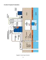
Page 38: ...35 Section 8 System Schematics Figure 8 1 Solar Sipper Schematic...
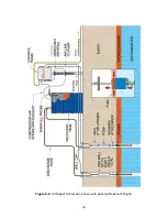
Page 39: ...36 Figure 8 2 AC Sipper Schematic shown with optional Desiccant Dryers...
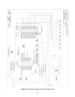
Page 40: ...37 Figure 8 3 8 Well Solar Sipper Internal Wiring Diagram...
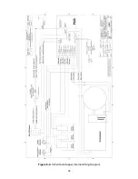
Page 41: ...38 Figure 8 4 3 Well Solar Sipper Internal Wiring Diagram...
Page 45: ...42 Notes...


