3
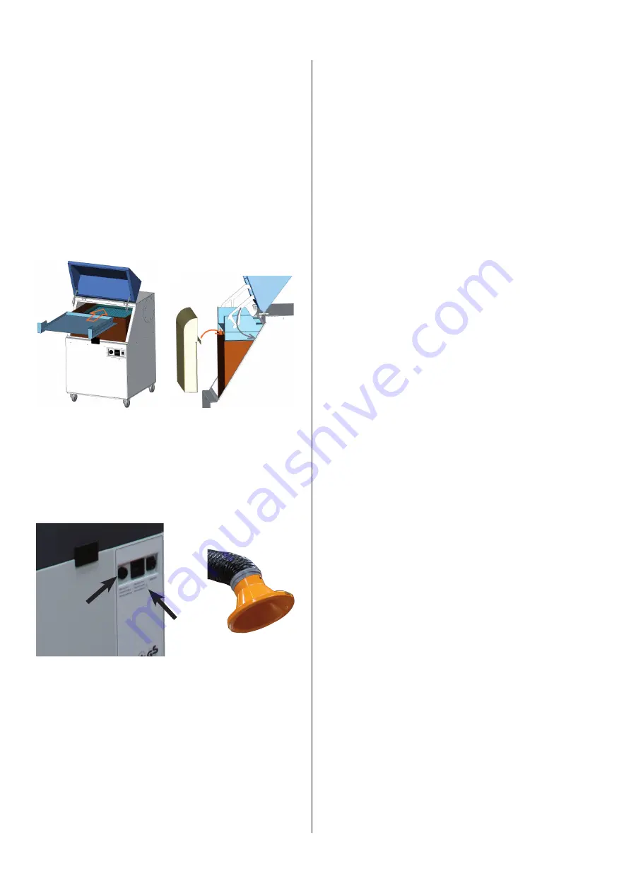
3.3 Installation of the baffleplate and
the dust collecting tray
The baffle plate is inserted into the filter unit in the
shown mounting direction (illustration on the left).
The baffle plate lies on top of the particle filter and is
pushed till it is adjacent to the back of the housing.
The dust collecting tray is installed in front of the baffle
plate (illustration on the right). The bracket of the dust
collecting tray must be hung in the front frame of the
particle filter.
Finally the maintenance door is to be closed. The clam-
ping brackets on the baffle plate must thereby move
inside the housing.
BA_Staubvorabscheidung filtoo_150105_GB.doc
4
15.04.2014
3.3 Installation of the baffle plate and the dust collecting tray
The baffle plate is inserted into the filter unit in the shown mounting direction (illustration on the left).
The baffle plate lies on top of the particle filter and is pushed till it is adjacent to the back of the housing.
The dust collecting tray is installed in front of the baffle plate (illustration on the right). The bracket of the
dust collecting tray must be hung in the front frame of the particle filter.
Finally the maintenance door is to be closed. The clamping brackets on the baffle plate must thereby
move inside the housing.
3.4 Resetting of the pressure switch
for the filter control
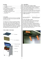
The W3 is equipped with a filter control as a standard
feature which monitors the degree of saturation of the
filter element. Details on this can be found in the sepa-
rate operating manual of the W3. The hooter (A) begins
to sound when the filter control is triggered.
4 Maintenance
The dust collecting tray must be cleaned at regular in-
tervals. The intervals depend on the produced quantity
of dust and thus cannot be predetermined.
The negative pressure in the device changes when the
dust pre-separator is used and the filter control would
then indicate a filter alarm at an early stage. Therefore,
it is necessary to reset the pressure switch accordingly.
Proceed as follows:
.
The baffle plate and the collecting tray must be
installed and the maintenance door must be closed
as specified in chapter 3.3
.
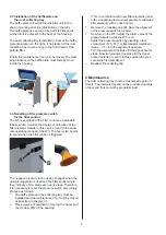
Place a piece of cardbord in front og the hood, so if
covers app. 90% of the opening
(This, in combiation with new filter elements gene
-
rates a negative pressure comparable to saturated
filter elements with an open hood.)
.
Remove the masking cap (B). Here the alignment
of the pressure switch is located.
.
Now turn on the W3. Adjust the alarm value of the
pressure switch while the W3 is on.
Adjust the pressure switch by inserting a torx
screwdriver (T25 -T27) or flat-bladed screwdriver
(size 2 - 3.5) into the alignment aperture.
Turn the alignment clockwise till the signal hooter
stops. Now turn counter-clockwise till the signal
hooter restarts to sound. In this position the pres-
sure switch is optimally set.
.
Reattach the masking cap.
A
B


