9
8
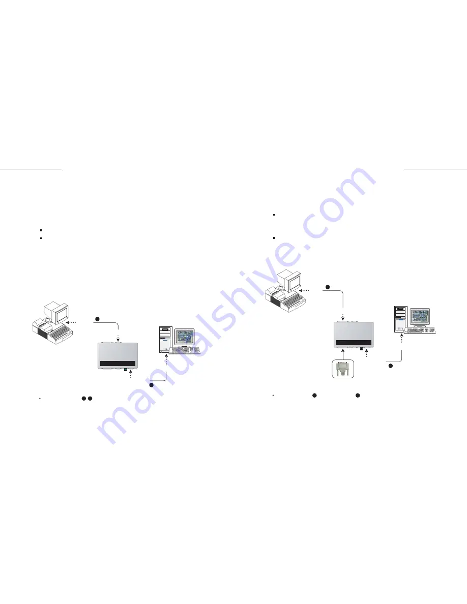
GV-Data Capture
GV-Data Capture
Serial Cash Register
1. Connect the GV-Data Capture box as illustrated below:
2. Follow the same settings as previously described in the
Serial POS
system
section.
2. Follow the same settings as previously described in the
Parallel POS
system
section.
The RS-232 cables supplied with the GV-Data Capture box.
2
1
In this manual, cash registers refer to those with receipt printers internally
connected. Cash registers may not be integrated to GV-systems, unless
with the following characteristics. Please check these characteristics
before actually connecting your cash register to the GV-system.
Cash Register Connection
Check if your cash register has an output port for a printer.
Connect a receipt printer to the output port and see if it functions well.
If it does, the integration is then possible.
Note:
If you see errors in printing (e.g. drop caps, character display errors), you may
encounter the same display problems when the GV-system overlays data on the
transaction scene.
GV-System
POS System
DB9
Female
DB9 Female
DB9 Male
DB9 Male
RS-232
2
RS-232
1
GeoVision GV-DATA CAPTURE
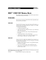
The two precautions taken when connecting the parallel cash register will
help ensure trouble-free operation.
Follow these steps to make the connection:
Make sure to connect a receipt printer or a terminator to the Capture box
(See the illustration below), or the GV-system cannot receive any
transaction data.
Make sure to restart your POS system after connecting the Capture box.
Parallel Cash Register
1. Connect the GV-Data Capture box as illustrated below:
The Parallel cable , the RS-232 cable and Terminator supplied with the
GV-Data Capture box.
2
1
Terminator
GV-System
POS System
DB25
Male
DB9 Female
DB9 Male
DB25 Female
RS-232
2
Parallel
1
GeoVision GV-DATA CAPTURE
Summary of Contents for DCV1-A-EN
Page 1: ...2005 01 GV Data Capture...


