3. Electric Wire
Wire Color
Function
Red DC
12V
Black GND
Yellow Beeper
Orange Green
LED
Light Red
Red LED
Green
Wiegand Data 0
White
Wiegand Data 1
Blue RS-485
+
Light Blue
RS-485 -
Gray N/A
Purple N/A
Brown N/A
Rear View
4. LED Indicator and Beeper
In standby mode, the LED is blue. When a card is read, the LED flashes green and the
beeper beeps once.
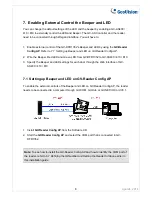
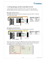
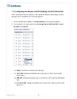
GV-DFR1352 comes with external control wires for Green LED, Red LED and Beeper. You
can connect these control wires to a GV-AS400 / 410 / 810 to allow the status of LED and
Beeper to be defined by the GV-AS400 / 410 / 810. For details on how to configure the
settings, refer to
7. Enabling External Control of the Beeper and LED
later in this installation
guide.
5. Connecting GV-DFR1352 to GV-AS Controller
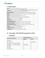
GV-DFR1352 can be connected to GV-AS100 / 110 / 120 / 210 / 400 / 410 / 810. To see how
many readers can be connected to a GV-AS Controller, refer to
The number of GV-DFR1352
supported by GV-AS Controllers
table at the end of this installation guide.
The connection between GV-DFR1352 and the controller varies with different controller
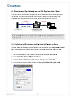
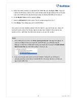
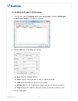
models. The following diagrams illustrate
how to connect GV-DFR1352 to GV-AS810
Controller
through Wiegand or RS-485 interface.
April 24, 2014
2


