3. Connecting the Camera
3.1 GV-FE110 / 111 / 2301 / 420 / 421 / 4301 / 520 / 521
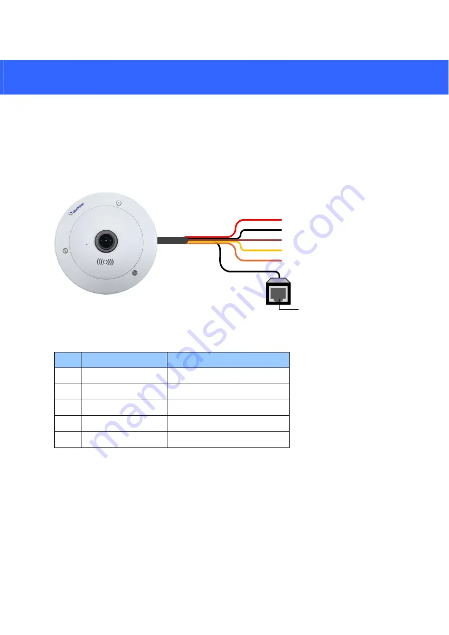
GV-FE series come with a 5-pin data cable that allows you to connect to the power and any
I/O devices.
Ethe rne t (P oE)
Digita l Output (Re d)
Digita l Input (Brown)
AC 24V / DC- (Ora nge )
GND (Bla ck)
AC 24V / DC+ (Ye llow)
Wire Definition
No.
Wire Color
Definition
1
Yellow
AC 24V+ / DC 12V+
2
Orange
AC 24V- / DC 12V-
3 Brown
Digital
Input
4 Red
Digital
Output
5 Black
GND
Connecting to Power
You can use a Power over Ethernet (PoE) adaptor to connect the GV-Fisheye IP Camera on
the network, and the power will be provided over the network cable. Alternatively, you can use
a standard network cable to connect the camera to your network, and then follow the steps
below to connect to power using the 5-pin data cable and the power adaptor provided.
19
1. Insert the yellow wire to the pin on the right-side of the terminal block and the orange wire
to the pin on the left-side of the terminal block.


