Introduction
31
1
1.3.5 Connecting the Camera
GV-IP LPR Camera supports three power specifications: DC 48V, AC 24V, High PoE (120 W).
Follow the steps below to connect your GV-LPC1100 to power, network and other wires
needed.
1.3.5.1 PoE Connection
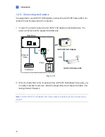
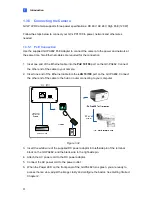
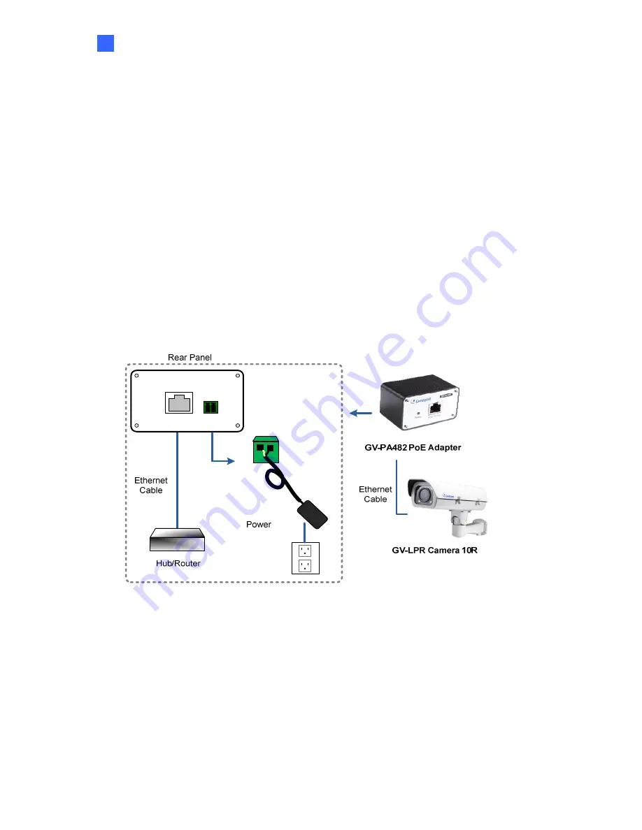
Use the supplied GV-PA482 PoE Adapter to connect the camera to the power and network at
the same time. Two Ethernet cables are required for the connection.
1. Inset one end of the Ethernet cable into the
PoE 10/100
port on the GV-PA482. Connect
the other end of the cable to your camera.
2. Insert one end of the Ethernet cable into the
LAN 10/100
port on the GV-PA482. Connect
the other end of the cable to the hub or router connecting to your computer.
LAN 10/100
Power IN
Figure 1-32
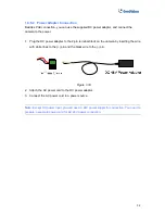
3. Insert the white wire of the supplied DC power adaptor into left-side pin of the terminal
block on the GV-PA482, and the black wire to the right-side pin.
4. Attach the AC power cord to the DC power adaptor.
5. Connect the AC power cord to the power outlet.
6. When the Power LED on the front panel of the GV-PA482 turns green, you are ready to
access the live view, adjust the image clarity and configure the basics.
See Getting Started
,
Chapter 2.


