________________________________________________
iii
English
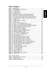
Table of Figures
Figure 1. WEEE label............................................................................. 2
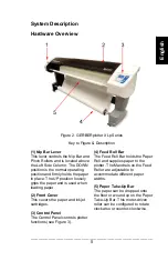
Figure 2. GERBERplotter XLp Series .................................................... 5
Figure 3. Control Panel .......................................................................... 6
Figure 4. Crate contents......................................................................... 7
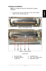
Figure 5. Component Box ...................................................................... 8
Figure 6. Right Side Column removed and balanced............................. 9
Figure 7. Attaching Crossbeam to Right Side Column ........................... 9
Figure 8. Two screws attaching Head Unit and Crossbeam ................ 10
Figure 9. Feed Motor Cable inside the Right Side Column .................. 10
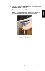
Figure 10. USB Cable .......................................................................... 11
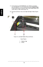
Figure 11. Rubber stop on Left Side .................................................... 12
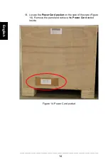
Figure 12. Power cord.......................................................................... 15
Figure 13. Paper roll and components ................................................. 16
Figure 14. Paper on Feed Roll Bar with Mandrel ................................. 16
Figure 15. Paper fed through the Nip Bar and Pinch Rollers ............... 17
Figure 16. Feeding paper toward front of plotter .................................. 18
Figure 17. Paper fed through plotter .................................................... 18
Figure 18. Plotter with paper installed .................................................. 19
Figure 19. Installed Inkjet Cartridges (XLp95) ...................................... 20
Figure 20. WinPlot Installation screen.................................................. 21
Figure 21. XLp Interface Installation screen ......................................... 22
Figure 22. Gerber Device Configuration............................................... 23
Figure 23. XLp Interface Icon ............................................................... 31
Figure 24. Machine Setting window, Plot tab ....................................... 32
Figure 25. Machine Setting window, Ink tab......................................... 33
Figure 26. Machine Setting window, Paper tab .................................... 34
Figure 27. Machine Setting window, System tab ................................. 35
Figure 28. Machine Setting window, Communication tab..................... 36
Figure 29. Machine Setting window, Calibration tab ............................ 37
Figure 30. Machine Setting window, MISC tab .................................... 38
Figure 31. X Gap calibration ................................................................ 38
Figure 32. Cartridge Overlap calibration .............................................. 39
Figure 33. Y Head calibration............................................................... 39
Figure 34. Y Gap calibration ................................................................ 40
Figure 35. XLp Interface Icon ............................................................... 42
Figure 36. WinPlot screen .................................................................... 43
Figure 37. Choose files to plot window................................................. 44
Figure 38. WinPlot box......................................................................... 45
Table 1. Safety labels............................................................................. 3
Table 2. Supplies and part numbers .................................................... 46
Table 3. Troubleshooting ..................................................................... 46
Table 4. Machine specifications ........................................................... 47
Summary of Contents for GERBERplotter XLp Series
Page 1: ......
Page 2: ......
Page 3: ......
Page 7: ......
Page 57: ......
Page 58: ......
Page 113: ......
Page 114: ......
Page 116: ...ii 1 3 7 21 WINPLOT 21 XLP 22 38 XLP 42 46 46 47 48...
Page 118: ...iv 41 X 41 42 1 2 Y 42 43 Y 42 44 XLp 44 45 WinPlot 45 46 46 47 WinPlot 47 1 3 2 46 3 46 4 47...
Page 121: ...3 XLp 1 Symbol Description 1...
Page 122: ...4...
Page 123: ...5 2 XLP 1 2 3 3 4 5 XLp...
Page 124: ...6 3 1 LCD 2 LCD LCD 3 LCD 4 LCD...
Page 125: ...7 2 1 XLp 4 5 4 XLp 5 1 2 3 4 4 72 1 82 5...
Page 126: ...8 2 6 6 1 2 USB 3 4 HP 5 6 7...
Page 127: ...9 3 7 7 4 8 5 6 4 5 8...
Page 128: ...10 7 9 9 1 8 10 10...
Page 129: ...11 9 USB B 11 10 USB USB 11 USB...
Page 130: ...12 11 12 12 12 12 1 2...
Page 131: ...13 13 110V 220V 13...
Page 132: ...14 14 14...
Page 133: ...15 14 15 15 16 I 15 1 2...
Page 134: ...16 17 16 16 1 2 3 18 17 17 1 2 3...
Page 135: ...17 19 20 21 22 23 18 18...
Page 136: ...18 24 19 25 a b 20...
Page 137: ...19 26 21 27 6 HP45 28 29 HP45 30...
Page 138: ...20 22 XLp95...
Page 141: ...23 Gerber 1 2 3 Gerber 25 4 Plotter 5 XLP USB PLOTTER XLP PLOTTER 6 7 ok 25...
Page 142: ...24 TCP IP TCP IP 1 XLp 2 XLp Interface 3 System Setting 26 XLp 27...
Page 143: ...25 4 IP Communication 27...
Page 144: ...26 5 6 lan scan 28 IP Communication...
Page 145: ...27 lan scan MAC 7 MAC MAC 8 IP 29 IP Communication...
Page 146: ...28 9 Connect 10 ok 30...
Page 147: ...29 11 IP 12 OK 31 13 XLp 14 15 1 3 XLp...
Page 148: ...30 16 32 32...
Page 149: ...31 1 XLp 2 XLp Interface 3 System Setting 33 XLp...
Page 150: ...32 Y 34...
Page 151: ...33 35...
Page 152: ...34 36...
Page 153: ...35 37...
Page 154: ...36 USB IP 38...
Page 155: ...37 X Y Y X Y Box 39 XLP95...
Page 156: ...38 X 1 X 39 X 2 40 3 7 2 4 X 3 5 6 40 X...
Page 158: ...40 Y 1 F R 39 Y 2 3 7 2 4 Y 3 5 6 43 Y...
Page 159: ...41 X Y Box Box 1m x 1 m 1mm 1mm Box 1 Box 39 Box 2 3 X Y 4 5 6 3 X Y 7 8 9...
Page 160: ...42 XLp XLp Winplot Accumark Accumark 1 XLp 2 3 XLp Plot Files 36 4 44 XLp...
Page 161: ...43 WinPlot 45 5 45 WinPlot...
Page 163: ...45 8 WinPlot 47 WinPlot GERBERplotter XLp plt...
Page 166: ...48...
Page 167: ...49 ON OFF XLp...
Page 168: ......
Page 169: ......
Page 170: ......

