background image

3

CAUTION – WARNING

1-WARNING!!

 PLEASE TAKE NOTICE THAT the suggested maximum pressure and/or 

temperature MUST NEVER BE EXCEEDED, as it may damage and/or cause ruptures and/

or leakages and/or even break the product, and present a potential hazard and danger to 

safety, health and/or property. Following are the technical data with respect to the installa-

tion of Gessi plumbing products.

►  

Working pressure should not be lower than 0,5 bar (7,25 psi) and not be higher than 5 

bar (72 Psi). In case of higher working pressure use a pressure reducer valve.

► 

Maximum test installation pressure: 8 bar (116 psi).

►  Avoid major pressure differences between hot and cold water supply. Differences in 

pressure, water with high mineral content, and soapy substances can corrode the inter-

nal and external parts of the hoses and slowly weaken the materials thereby causing 

leakage.

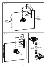
► Maximum working temperature for Gessi products is 70 °C (158 °F).

2-WARNING!!

 PLEASE TAKE NOTICE THAT the product should never be used as a tool, 

hammer or for any purposes other than the one it has been designed for.

3-WARNING!!

 PLEASE TAKE NOTICE THAT the product should always be installed and 

tested by a professional plumber.

4-WARNING!!

 PLEASE TAKE NOTICE THAT electric cables should never be attached to 

the product as they may present a health and safety hazard.

5-WARNING!!

 PLEASE TAKE NOTICE THAT heavy objects should never be placed on 

or dropped on the product as they may damage the same and cause splinters, which may 

present a health and safety hazard.

6-WARNING!!

 PLEASE TAKE NOTICE THAT the instructions manual should carefully read 

before installation and the installation procedure provided therein must be properly followed 

and complied with.

7-WARNING!!

 PLEASE TAKE NOTICE THAT during installation the use of excessive force 

should be avoided in order to prevent damage to the product and/or its components and 

pieces. NEVER force a component or piece into another. NEVER force screws or over 

tighten screws.

Summary of Contents for OVALE 26938

Page 1: ...ROGRAMMA MISCELAZIONE BAGNO BATH MIXING PROGRAM PROGRAMME DU MITIGEUR POUR LA SALLE DE BAIN BAD MISCHUNGSPROGRAMM PROGRAMA MEZCLADORES BAÑO OVALE Art 26938 TERMOSTATICO INCASSO BUILT IN THERMOSTATIC MIXER ...

Page 2: ...8 F 2 ATTENZIONE VI PREGHIAMO DI TENER CONTO CHE il prodotto non deve mai essere utilizzato come utensile martello o per un qualsiasi altro scopo diverso da quello per cui è stato progettato 3 ATTENZIONE VI PREGHIAMO DI TENER CONTO CHE il prodotto deve essere sem pre installato e testato da un idraulico professionista 4 ATTENZIONE VI PREGHIAMO DI TENER CONTO CHE i cavi elettrici non devono mai ess...

Page 3: ...for Gessi products is 70 C 158 F 2 WARNING PLEASE TAKE NOTICE THAT the product should never be used as a tool hammer or for any purposes other than the one it has been designed for 3 WARNING PLEASE TAKE NOTICE THAT the product should always be installed and tested by a professional plumber 4 WARNING PLEASE TAKE NOTICE THAT electric cables should never be attached to the product as they may present...

Page 4: ...Prima di procedere con il montaggio delle parti esterne è importante prendere visione degli ingombri mostrati in figura per evitare spiacevoli inconvenienti di mancanza di spazio INSTALLATION AND ASSEMBLY OF THE THERMOSTAT WALL MIXER WITH NPT CONNECTIONS OUTER PARTS Fig 1 It is important to know the overall sizes shown in the figure before starting with the assembly of the outer parts in order to av...

Page 5: ...5 1 2 Fig 16 Fig 2 RICAMBISTICA per articolo completo 26937 1 Cartuccia termostatica 2 Maniglia Fig 2 SPARE PARTS for complete article 26937 1 Thermostat cartridge 2 Handle Fig 2 ...

Page 6: ...a di comando I la maniglia di comando con grano di fissaggio pre montato L la chiave a brugola da 1 8 e tappino copri grano della maniglia Fig 3 Inside the pack there are the following A the cover plate with pre assembled fixing dowels B the cover hood C the cover ring D the extension for the thermostat cartridge E the extension with inner toothing F the plastic nut G the ring with degree indication...

Page 7: ...7 OPEN COLD WATER OPEN HOT WATER 100 F 38 C 100 F 38 C 100 F 38 C Fig 18 Fig 19 Fig 4 Fig 5 ...

Page 8: ...tra per aumentare la temperatura o verso destra per ridurla fino ad ottenere la temperatura prevista TEMPERATURE ADJUSTMENT Fig 4 5 The thermostat body has been adjusted by the manufacturer at a temperature of 100 F 38 C It is recommended to carry out the calibration again before continuing with the assembly of the outer parts Open the installation and control the outlet water temperature if you do...

Page 9: ...9 Allen key 1 8 Allen key 1 8 Fig 21 Fig 22 Fig 23 Fig 20 Fig 6 Fig 7 Fig 8 Fig 9 ...

Page 10: ...iti nell anello della stessa e collocare il rosone di copertura fino contro la piastra A questo punto il foro nella parete deve essere completamente coperto INSTALLATION OF THE OUTER PARTS Fig 6 Screw the cover ring to the body built in in the wall Fig 7 Place inside the cover ring the extension for the thermostat cartridge and the extension with inner toothing Both have to be connected well to the...

Page 11: ...sare la maniglia di comando mediante l apposito grano di fissaggio e chiudere il foro sulla maniglia con il tappino in dotazione Fig 10 Introduce the ring with the degree indication keeping the control pushbutton upwards and fix it screwing the fixing kit for the handle in the illustrated sequence Fig 11 Fix the control handle by means of the proper fixing dowel and close the hole on the handle with t...

Page 12: ...12 Allen key 1 8 Allen key 1 8 Allen key 1 8 Allen key 1 8 Fig 26 Fig 27 Fig 28 Fig 29 Fig 12 Fig 13 Fig 14 Fig 15 ...

Page 13: ...rosone di copertura e la piastra svitando i grani di fissaggio che la fissano al corpo Fig 15 Togliere la ghiera in plastica REPLACEMENT OF THE THERMOSTAT CARTRIDGE Check the closure of the water net before carrying out this operation Fig 12 Remove the small cap which covers the hole where the fixing dowel of the handle has been introduced Unscrew the fixing dowel and take out the control handle Fig 1...

Page 14: ...14 Key 15 16 Fig 30 Fig 31 Fig 32 Fig 16 Fig 17 Fig 18 ...

Page 15: ...llo di copertura Fig 18 Utilizzando la chiave indicata in figura svitare la cartuccia termostatica danneggiata Fig 16 Remove the two extensions introduced in the cover ring Fig 17 Unscrew the cover ring Fig 18 Unscrew the damaged thermostat cartridge by means of the wrench indicated in the figure ...

Page 16: ...16 OPEN COLD WATER OPEN HOT WATER 100 F 38 C 100 F 38 C Key 15 16 Fig 33 Fig 34 Fig 36 Fig 35 Fig 19 Fig 20 Fig 22 Fig 21 ...

Page 17: ...re tutte le parti esterne riferirsi alle immagini e ai testi da Fig 6 a Fig 11 INSTALLAZIONE PARTI ESTERNE Fig 19 Introduce the new cartridge in the proper seat and fix it with the proper wrench Fig 20 21 Calibrate the thermostat cartridge at 100 F 38 C refer to the images and the texts in Fig 4 5 TEMPERATURE ADJUSTMENT Fig 22 Re assemble all the outer parts refer to the images and the texts from F...

Page 18: ...e riferirsi alle immagini e ai testi da Fig 6 a Fig 11 INSTALLAZIONE PARTI ESTERNE CARTRIDGE CLEANING Fig 23 It is recommended to carry out the cleaning of the cartridge in order to remove the limestone transported by the water which could damage it if the water of the proper installation presents a high limestone level then it is recom mended to carry out regular cleaning In order to carry out th...

Reviews: