27
NRG 16-51, NRG 17-51, NRG 19-51 - USA - Installation & Operating Manual -
850692-00
l
Low water LW
m
Reducer
n
High water HW
o
Electrode spacing
≥
0.55 in (14 mm)
(air gaps and creepage paths)
CD Center distance of standpipes
Electrical connection
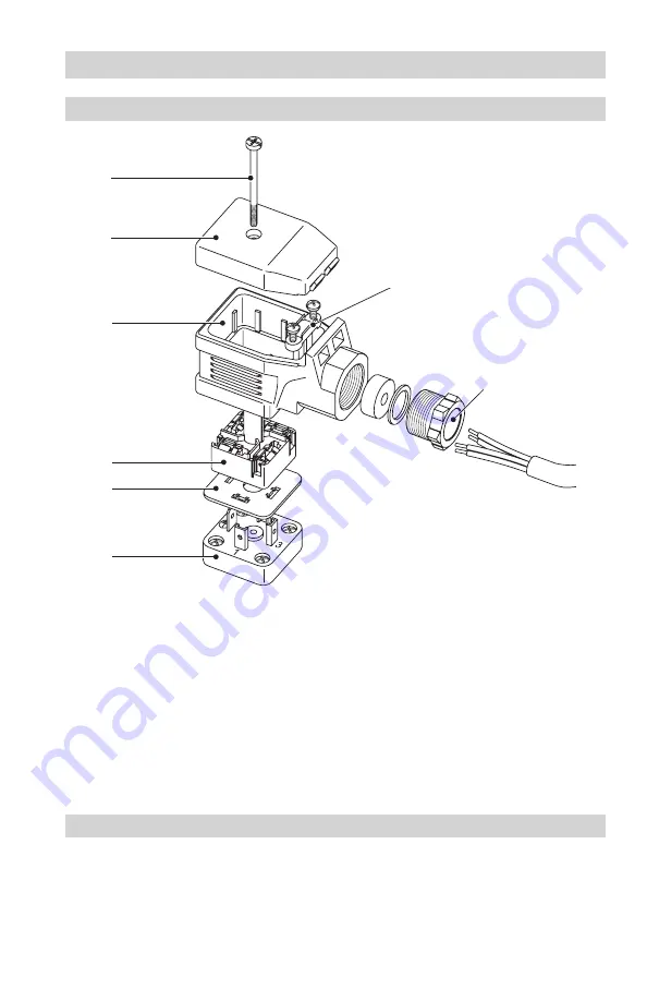
NRG 16-51, NRG 17-51, NRG 19-51 with four-pole connector
Fig. 20
z
y
v
w
x
A
Key
v
Screw M 4
w
Cover
x
Upper part of connector
y
Connection plate
z
Insulating plate
A
Level electrode contact plate
B
Cable clamp
C
Cable gland M 19 (PG 11)
B
C


