18
d
Mains voltage
e
MAX limit contact (MAX alarm)
f
Pump control
Fill control:
= Pump OFF
= Pump ON
Discharge control: = Pump ON
= Pump OFF
g
MIN limit contact (MIN alarm)
h
Actual value output 420 mA
k
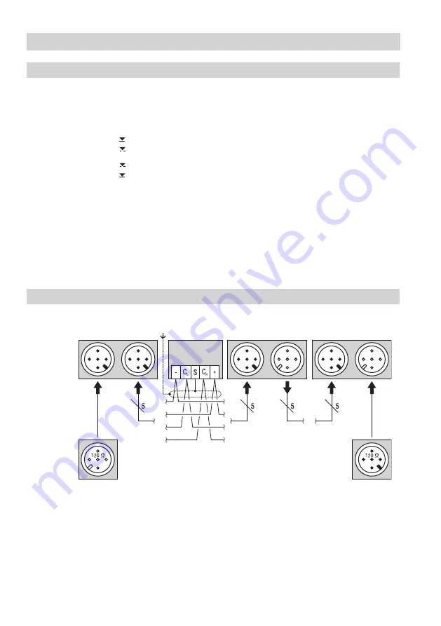
Terminating resistor 120 Ω, RES 1 or RES 2
l
Twisted pair control cable for CAN bus line
m
Valve actuator
n
Feedback potentiometer 1000 Ω actuator
Key
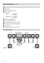
Electrical Connection
– continued –
CAN bus wiring diagram
Fig. 14
RES 2
CEP*)
NRS, NRR, LRR,
TRS, URB 1
URB 2
NRG, LRG,
EF, URZ
TRV
RES 1
*) Central earthing point


