11
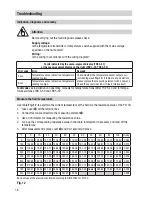
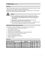
Note
n
To install the temperature sensor in a pipe, weld the elbow
c
onto it. This ensures that
the temperature sensitive part
2
,
6
of the temperature sensor is immersed in the
fluid against the flow direction
Fig. 7 and Fig. 8
n
Install the temperature sensor such that the temperature-sensitive part
2
,
6
is
permanently immersed in the fluid.
Fig. 2 and Fig. 4
n
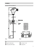
The seating surfaces of the threaded standpipe or the flange provided on the vessel
must be accurately machined, see
Fig. 3.
n
Do not completely insulate the temperature sensor. See examples of installation in
vessel
Fig. 5 and Fig. 6
n
Only qualified welders certified according to EN 287-1 may weld welding sleeves into
lines or vessels.
Attention
Installation
TRG 5-63 and TRG 5-64
1. Check seating surfaces.
Fig. 3
2. Put joint ring
3
onto the sealing surface of the threaded standpipe or flange provided on the
vessel (select joint ring material according to the range of application).
Fig. 3
3. Screw in the temperature sensor and fasten it with an open-end spanner 27 mm A. F. The torque
required
when cold is 150 Nm.
TRG 5-65, TRG 5-66, TRG 5-67 and TRG 5-68
1. Provide a penetration for the socket-weld end on site.
2. Unscrew the upper part of the temperature sensor from the welding sleeve
5
.
3. Weld the welding sleeve
5
in place. Arc-weld the equipment in place, applying welding process
111 and 141 in accordance with ISO 4063.
4. Put copper ring onto welding sleeve
5
and screw the upper part of the temperature sensor into
the welding sleeve
5
. Fasten the upper part of the temperature sensor when cold with an open-
end spanner (17 or 24 mm A. F.).
Tools
n
Open-end spanner 17 mm A. F.
n
Open-end spanner 24 mm A. F.
n
Open-end spanner 27 mm A. F.
- continued -


