background image


28 

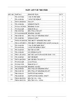
PART LIST FOR TMD-P26B 


KEY NO 

PART NO 

DESCRIPTION 

Q'TY 

P1113-0003500 

ADJUSTING KNOB 

P01-044200A 

KNOB FIXING BRACKET 

P01-044210B 

TENSION INDICATOR PLATE   

P02-028790B 

PRESS WHEEL 

P1104-18AXK30470 

P1104-19AS30470 

BEARING 

WASHER     

P1201-0001700 

PRE-STRETCH SPRING 

P1104-19AS30470  WASHER 

P01-044220A 

RELEASE LEVER   

P02-028800A 

BRAKE PAD 

10 

P06-0011900 

BRAKE PAD 

11 

P02-0287800 

HANDLE BAR SHAFT 

12 

P01-0441700 

HANDLE BAR LEVER 

13 

P06-0047400 

HANDLE BAR 

14 

P01-044230A 

HANDLE BAR POSITON SHAFT 

15 

P0302-020000200 

P0319-10P26B08 

PHOTO SENSOR A3R-2MX 

PHOTO SENSOR A3R-2MX w/ connector 

16 

P01-0441300 

PHOTO SENSOR SEAT 

17 

P01-0441800 

CARRIAGE COVER (REAR) 

18 

P01-0441900 

CARRIAGE COVER (FRONT) 

19 

P01-0442400 

FIXING PLATE (REAR) 

20 

P1122-0000200 

FIXING BALL (M8) 

21 

P01-0442600 

FIXING PLATE (FRONT) 

22 

P1104-026203ZZ0  BEARING 

23 

P02-028810A 

BEARING SEAT   

24 

P08-000780B 

STRETCH ROLLER   

25 

P01-044160B 

CARRIAGE BASE   

26 

P08-0001000 

ROLLER SET 

27 

P0311-060001200 

LIMIT SWITCH VL-8108 

28 

P0304-010005600 

CONNECTOR HOUSING, 12P 15A 

29 

P01-0442500 

CABLE BRACKET 

30 

P0311-060001400 

LIMIT SWITCH ML-7312 

31 

P1201-0008400 

FOOT SAFETY PEDAL SPRING   

Summary of Contents for GPPW-1500B

Page 1: ...PALLET STRETCH WRAPPING MACHINE MODEL TMD P26B OPERATION MANUAL 20220406 ERP part no GPPW 1500B OPERATION MANUAL ...

Page 2: ...N 5 3 OPERATION DESCRIPTION 6 3 1 INSTALLATION 6 3 2 REMINDER OF INSTALLATION 8 3 3 OPERATION OF CONTROL PANEL 9 3 4 OPERATION DESCRIPTION 10 3 5 OPERATION CYCLE 12 4 ELETRICAL 15 4 1 ELECTRIC CAPACITY 15 4 2 ELECTRIC DIAGRAM 16 5 TROUBLE SHOOTING 20 5 1 GENERAL ADJUSTMENT 21 5 2 TROUBLE SHOOTING 22 6 PART LIST 23 6 1 SEAT 23 6 2 TOWER 25 6 3 ELEVATOR 27 6 4 CONTROL BOX 30 ...

Page 3: ...ual of the machine need 2 Machine standard power is AC110v 230v 10 3 Machine standard power Hertz is 50 60 Hz 2 4 Machine is workable under the temperature between 0 45 5 Make sure the wire is tidy on the ground 6 There should not have vibration beside the machine during the installation and make sure to ground is flat 7 Read and follow the instruction of the installation ...

Page 4: ...al manual carefully 2 Make sure there is no object put on the power cable 3 Make sure there is no object put on the upper elevator unit 4 Avoid any damp object or water around the electric parts 5 Avoid film winded into the turntable 6 Do not stand on or across the machine during operation 7 When the problem occurs please check the section of 5 Trouble shooting ...

Page 5: ...ing size 1050x1050mm Max Loading weight 1200Kg Film stretch Infinite manual adjust Max film spec 250x500mm Turntable height 76mm Ramp slope spec 1165x1000mm Machine size 2300x1500x2346 mm Machine net weight 335Kg Standard option 1 65 meters turntable dia Max Loading Weight 1650kg 2 6 meters wrapping height 3 0 meters wrapping height Ramp ...

Page 6: ...4 2 2 MACHINE DIMENSION ...

Page 7: ...5 2 3 Machine Description ...

Page 8: ...a Loosing 4 screws at the end of masters Do not unscrew the sliding shaft leave inside the track b Lift up the master Step 1 c Sliding the master towards turntable until the sliding shaft move into locking position Step 2 d Master is in position to be fully lifted and tighten all screws Step 3 1 2 3 ...

Page 9: ...7 3 Connect the motor plug to the main control by referring to the diagram below Machine is ready to be connecting to the power cable with the socket by an 110V 230V power ...

Page 10: ... the engineers must make sure all 4 screws are properly installed underneath the tower 1 by carriage side and 3 by the motor sides Motor Cover After all the connections are complete please carefully install the motor cover to cover up all the wire connections and the motor on the base of the machines ...

Page 11: ...9 3 3 OPERATION OF CONTROL PANEL ...

Page 12: ...r is ON when light illuminates Machine Running LED Continue Flash Power Cut circuit EMG KEY ETC Flash Twice C MODE SELECTIONS This selector is to choose the number of top and bottom Mode 1 Top 2 wraps bottom 3 wraps Mode 2 Top 3 wraps bottom 4 wraps D START Press the button to get automatic program running ...

Page 13: ... button to resume back to operation F EMERGENCY STOP Press the button for emergency stop For security consideration the turntable will not be stopped instantly as the EMG STOP switch is pressed As the turntable power is switched off the break will be release too Turntable will be stopped in 10 70 It depends on the weight load ...

Page 14: ...s E button to pause the machine and press D button to resume back to operation 5 When the wrapping cycle is finished the carriage will return back to the bottom of the machine and the machine will automatically stop 6 Return to Operation Cycle step 2 Start the Button Wrapping Cycle 7 Please turn off the Main Power Switch A into off position when the machine is no longer in use Please press the eme...

Page 15: ...nob Turn the knob clockwise to increase the tension Counterclockwise to decrease the tension Adjust and set the indicate needle on the green zone can get the stretch tension is 1 meter Film stretched to be 1 65 meters Quick Release Handle Tension Adjusting Knob Tension Indicator ...

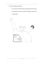
Page 16: ...14 3 Film Quick Release description Pull up the quick release handle upon applying film to the loads Push down the quick release handle to engage the brake during the wrap cycle ...

Page 17: ...4 1 ELECTRIC CAPACITY 1 Power Consumption Turntable motor 0 4 KW Elevator Motor 0 4KW Control wiring box DC 24V Machine Power Use 0 85 KW Power Socket need 1 KW 2 Power Cable 1 25 2 3 Machine input 110V 230V 1 PHASE ...

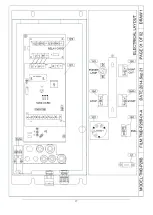
Page 18: ... FILM CARRIAGE ML 7312 1 1S7 1S7 P0302 020000200 P0319 10P26B08 PHOTO EYE A3R 2MX PHOTO EYE A3R 2MX w connector 1 1S5A P0311 060001210 TOP LIMIT TZ 8108 1 1S6 P0311 060001210 BOTTON LIMT TZ 8108 1 1S7A 1S7A P0302 010002000 P0319 10P26B15 TURNTABLE HOME SENSOR PM12 04P 3M TURNTABLE HOME SENSOR PM12 04P 3M w connector 1 1 1S3A 1S7 1S5A 1S6 1S3B 1S7A ...

Page 19: ...17 ...

Page 20: ...18 ...

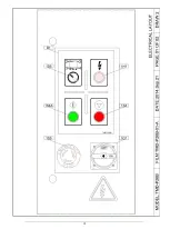
Page 21: ...020002800 EMERENCY STOP SKB2ES524 1B R w connector 1 1S3A P0311 020000100 CARRIAGE BOX DOOR SWITCH TZ 93BPG 1 1S4 P0313 020002600 STOP BUTTON COVER Contact SKB2EA42 1A R 1 1S4A P0313 020002500 START BUTTON COVER Contact SKB2EA31 1A G 1 1S5 P0313 020002700 COUNT SWITCH SKB2 ED21 1A 1 1P8 P0309 010002000 RELAY CARD 1 A1 P0311 030000100 CARRIAGE BOX DOOR KEY TZ93 K3 1 B1 P1002 0006700 PANEL STICKERS ...

Page 22: ...20 ...

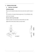
Page 23: ...w and then loosen the motor seat M10 screw 4 pcs Turn the M10 on the seat until get enough tension Turn and tight the motor seat screw 4 pcs again Elevator unit driving chain adjust Adjust the elevator to proper position and take off the cover tower Adjust the M10 screw Up and down to proper tension ...

Page 24: ...nge microprocessor board 1 Check the proximity S W sense If it is no problem adjust the sensing plate 2 Check the top and bottom limit 4 2 ELECTRIC DIAGRAM 1S5A 1S6 As doing AUTO RUN the CARRIAGE unit goes up and over the package height Photo eye gets sense from another material except package Photo sensor gets sense from another light source 1 Move away other objects Avoid the light source 2 Chec...

Page 25: ...23 6 PART LIST 6 1 SEAT 1 2 3 4 5 6 7 8 9 10 11 12 13 14 15 16 17 18 19 20 21 22 23 ...

Page 26: ...R PM12 04P PROXIMITY SENSOR PM12 04P connector 1 1 11 P01 044030A P01 045190A 1 5M TURNTABLE SEAT 1 65M TURNTABLE SEAT 1 1 12 P01 0440600 MOTOR COVER 1 13 P01 0440400 COVERING PLATE 1 14 P0501 0014200 MOTOR 1 2HP 3 PH AC200V 380V 1 50 1 15 P01 0440500 MOTOR BASE 1 16 P0703 0007000 MOTOR BELT PULLEY 5 1 17 P1105 0242B C CLIP R 42 1 18 P1105 0117B RING STW 17 1 19 P1104 026203ZZ0 BEARING 6203ZZ 2 20...

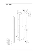
Page 27: ...25 6 2 TOWER ...
Page 28: ...2AZ NUT M12 2 9 P1103 011224D5Z WASHER M12 4 10 P01 0018700 CHAIN ADJUST SEAT 1 11 P1102 0106BZ NUT M6 2 12 P1101 0908020AN SCREW M8x20L 2 13 P02 0289000 SPROCKET WHEEL SHAFT 1 14 P1105 0235B C CLIP R 35 1 15 P1104 026002ZZ0 BEARING 6002ZZ CWB 1 16 P0702 0000200 SPROCKET WHEEL Lower 1 17 P01 044070A P01 0452100 TOWER 2 2M TOWER 2 6M 1 1 18 P01 0441000 LIMIT STOP 1 19 P1101 0508120AN SCREW M8x120L ...

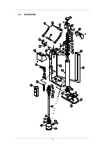
Page 29: ...27 6 3 ELEVATOR 1 2 3 4 5 6 7 8 5 9 10 11 12 13 14 15 16 17 18 19 20 21 22 23 24 25 22 23 26 26 27 28 29 30 31 32 33 34 35 36 37 35 36 38 36 35 37 39 40 41 42 ...

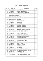
Page 30: ...1 044230A HANDLE BAR POSITON SHAFT 1 15 P0302 020000200 P0319 10P26B08 PHOTO SENSOR A3R 2MX PHOTO SENSOR A3R 2MX w connector 1 1 16 P01 0441300 PHOTO SENSOR SEAT 1 17 P01 0441800 CARRIAGE COVER REAR 1 18 P01 0441900 CARRIAGE COVER FRONT 1 19 P01 0442400 FIXING PLATE REAR 1 20 P1122 0000200 FIXING BALL M8 2 21 P01 0442600 FIXING PLATE FRONT 1 22 P1104 026203ZZ0 BEARING 2 23 P02 028810A BEARING SEAT...

Page 31: ...700 FOOT SAFETY PEAL 1 34 P1101 0506040AN SCREW M6X40L 1 35 P1105 0224B C CLIP R 24 3 36 P01 0441500 WASHER 45x25 5x2t 3 37 P06 0047500 FILM MANDREL 2 38 P02 0288200 FILM SHAFT SEAT 1 39 P06 0048300 FILM SEAT BASE SHEET 1 40 P01 0441400 FILM STOPPER 1 41 P02 028830A FILM SEAT 1 42 P1101 0104006AZ SCREW M4X6L 2 ...

Page 32: ... 1 P01 044300A CONTROL BOX 1 2 P01 006580A WIRING PLATE 1 3 P01 0442900 CONTROL BOX COVER 1 4 P01 0021600 HINGE R 2 5 P1118 010000200 P1118 030000100 P1118 020000100 LOCK C 403 1 LOCK PLATE KEY 2 2 2 6 P0311 030000100 KEY TZ93 K3 1 7 P0311 020000100 SAFETY SWITCH TZ 93BPG 1 ...

Reviews: