background image


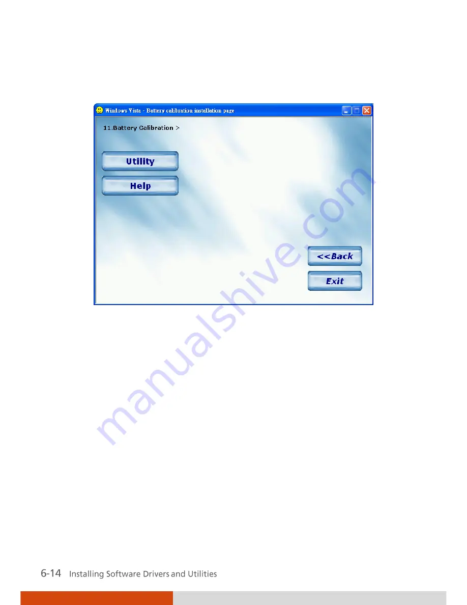
Battery


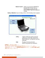
Upon clicking this button, the following screen 

Calibration


appears. 


Utility 

Installs the battery pack automatic 
calibration utility that includes the 
Battery Monitor and Battery Learning 
programs. 

Help 

Displays the instructions for 
performing a battery calibration. 

Summary of Contents for M230

Page 1: ...Rugged Mobile Computing Solutions M230 USER S MANUAL ...

Page 2: ...May 2009 TRADEMARKS All brand and product names are trademarks or registered trademarks of their respective companies NOTE The information in this manual is subject to change without notice ...

Page 3: ...abled power management features Earning the ENERGY STAR When every home office is powered by equipment that has earned the ENERGY STAR the change will keep over 289 billion pounds of greenhouse gases out of the air If left inactive ENERGY STAR qualified computers enter a low power mode and may use 15 watts or less New chip technologies make power management features more reliable dependable and us...

Page 4: ...nagement sleep settings on computers and monitors can result in much savings annually Remember saving energy prevents pollution Because most computer equipment is left on 24 hours a day power management features are important for saving energy and are an easy way to reduce air pollution By using less energy these products help lower consumers utility bills and prevent greenhouse gas emissions ...

Page 5: ...nents 1 6 Rear Components 1 8 Right Side Components 1 9 Left Side Components 1 10 Bottom Components 1 11 Top open Components 1 12 Chapter 2 Operating Your Computer 2 1 Starting and Stopping the Computer 2 2 Starting the Computer 2 2 Stopping the Computer 2 2 Using the Keyboard 2 4 Typewriter Keys 2 4 Cursor Control Keys 2 5 Numeric Keypad 2 5 Function Keys 2 6 Fn Key 2 6 Hot Keys 2 6 Using the Tou...

Page 6: ... 28 Using the Bluetooth Feature Optional 2 29 Using the GPS Feature Optional 2 32 Turning On Off the GPS 2 32 Chapter 3 Managing Power 3 1 AC Adapter 3 2 Battery Pack 3 3 Charging the Battery Pack 3 3 Initializing the Battery Pack 3 4 Checking the Battery Level 3 4 Replacing the Primary Battery Pack 3 5 Installing the Secondary Battery Pack 3 6 Battery Low Signals and Actions 3 7 Power Management ...

Page 7: ... to Use the Driver Disc 6 2 Installation for Windows XP 6 3 Drivers on the First Page 6 3 Drivers on the Second Page 6 5 Installation for Windows Vista 6 9 Drivers on the First Page 6 9 Drivers on the Second Page 6 12 Using Special Utilities 6 15 Touchscreen Utility 6 15 OSD for Hot Key Operations 6 16 Chapter 7 Caring for the Computer 7 1 Protecting the Computer 7 2 Using an Anti Virus Strategy 7...

Page 8: ...8 7 WLAN Problems 8 7 Modem Problems 8 9 Optical Drive Problems 8 9 PC Card Problems 8 10 Power Management Problems 8 11 Printer Problems 8 11 Software Problems 8 12 Sound Problems 8 12 Startup Problems 8 13 Other Problems 8 13 Resetting the Computer 8 14 Appendix ASpecifications A 1 Appendix B Regulatory Information B 1 On the Use of the System B 2 Class B Regulations B 2 Safety Notices B 3 On th...

Page 9: ...ongratulations on purchasing this rugged notebook computer This chapter first tells you step by step how to get the computer up and running Then you will find a section briefly introducing the external components of the computer ...

Page 10: ... Car adapter option Extra battery pack option Touchscreen pen option Vehicle docking option Office docking option Inspect all the items If any item is damaged or missing notify your dealer immediately Keep the shipping carton and packing materials in case you need to ship or store the computer in the future Connecting to AC Power The computer operates either on the external AC power or internal ba...

Page 11: ...tive 1 Make sure that the computer is turned off 2 Plug the DC cord of the AC adapter to the power connector of the computer 3 Plug the female end of the AC power cord to the AC adapter and the male end to an electrical outlet ...

Page 12: ...ctrical outlet to the AC adapter and onto your computer Now you are ready to turn on the computer Opening and Closing the Cover Open the top cover by pulling on the cover latch and lifting up the cover You can tilt the cover forward or backward for optimal viewing clarity ...

Page 13: ... is connected to AC power 2 Press the power button 3 Each time the computer is turned on it performs a Power On Self Test POST and the operating system such as Windows should start Turning Off To turn off the computer power use the Shut Down command of your operating system ...

Page 14: ...ecurity P 7 3 Touchscreen Pen option Provides a convenient way to use the touchscreen Can be stretched for better grip and handling P 2 12 Handle Allows you to carry your computer for an easy grip Device Indicators Show current status of the computer s devices AC power indicator Glows green when computer is using AC power Glows red when the computer using AC power is in Sleep mode P 3 2 ...

Page 15: ...amber when the battery is being charged P 3 3 Battery Power Indicator Glows green when computer is using battery power Blinks amber when the battery is almost completely discharged P 3 3 Combo DVD Dual drive in use indicator P 2 15 Wireless LAN Local Area Network indicator P 2 25 Wireless modem indicator P 2 28 Wired LAN indicator P 2 23 ...

Page 16: ... RJ 11 Connector Connects the telephone line P 2 27 RJ 45 Connector Connects the LAN cable Includes a Link Indicator and an Active Indicator P 2 23 VGA Port Connects an external CRT monitor P 4 2 Parallel Port Connects a parallel device such as a printer P 4 4 Audio Output Connector Connects a set of headphones external speakers with amplifier or an audio recording device P 2 22 Microphone Connect...

Page 17: ...Accepts a PC card for additional functions P 4 9 USB Ports Each of the two ports connects a USB device such as a USB floppy drive USB flash disk printer digital camera joystick and more P 4 3 IEEE 1394B Port Connects a 1394B device such as a mass storage device digital video DV camcorder or a digital audio device P 4 8 or PS 2 Port Connects a PS 2 keyboard or mouse ...

Page 18: ...isc for installing or loading software accessing data and playing music video P 2 15 or Secondary Battery Pack You can purchase a secondary battery pack to be installed here for prolonged battery operating time P 3 6 Hard Disk Drive Compartment Contains the hard disk drive of your computer P 2 14 ...

Page 19: ...21 Memory Slot Contains the memory slot for expanding the memory size of your computer P 4 11 Docking Connector POGO For connecting to a Port Replicator or Car Mount both are available as an option Release Knob Allows you to remove the module optical drive or secondary battery pack installed in the computer P 2 16 P 3 6 ...

Page 20: ...ponent Description See Also Docking Antenna Connector Connects to an external antenna from docking SIM Card Slot Contains the SIM card slot for using the GSM GPRS CDMA WCDMA function P 2 28 Top open Components ...

Page 21: ...omputer s devices Power indicator Glows green when the computer is turned ON Glows amber orange when the computer is in Standby Sleep mode P Hard disk drive in use indicator Blinks green when the hard disk drive is active Blinks red when the hard disk heater is on P 2 14 Scroll Lock indicator P 2 4 Num Lock indicator P 2 5 Caps Lock indicator P 2 4 LCD Screen Displays the output of the computer Ca...

Page 22: ......

Page 23: ...es information about the use of the computer If you are new to computers reading this chapter will help you learn the operating basics If you are already a computer user you may choose to read only the parts containing information unique to your computer ...

Page 24: ...t on This process is called booting Stopping the Computer When you finish a working session you can stop the computer by turning off the power or leaving the computer in Standby Sleep or Hibernation mode To stop in this mode Do this To start up or resume again Off Follow the shutdown procedure of your operating system This can prevent loss of unsaved data or damage to your software programs If the...

Page 25: ... the power button Press any key Hibernation Depending on your settings in Windows you can place the computer in Hibernation mode by Closing the display cover Pressing the Fn F12 hot key Pressing the power button Press the power button If you choose to stop in Standby Sleep or Hibernation mode you can return to where you left off the next time you start up the computer See Power Management in Chapt...

Page 26: ...ction keys Typewriter Keys Typewriter keys are similar to the keys on a typewriter Several keys are added such as the Ctrl Alt Esc and lock keys for special purposes When the lock keys aps Lock and Num Lk are pressed their corresponding indicators light up The Control Ctrl Alternate Alt key is normally used in combination with other keys for program specific functions The Escape Esc key is usually...

Page 27: ...Cursor Control Keys Numeric Keypad A 15 key numeric keypad is embedded in the typewriter keys as shown next ...

Page 28: ...ther key to perform the alternative function of a key The letter Fn and the alternative functions are identified by the color of blue on the keytop To perform a desired function first press and hold Fn then press the other key Hot Keys Hot keys refer to a combination of keys that can be pressed any time to activate special functions of the computer Most hot keys operate in a cyclic way Each time a...

Page 29: ...ing the system with CRT LCD LCD CRT CRT NOTE Fn F9 will not work when playing a DVD MPEG movie Using the VGA utility s Graphics Properties to switch the display output is not allowed Display switching when in full screen maximize view DOS mode is not allowed If the display mode is set to 256 colors or lower or in DOS mode there will be only two modes for selecting CRT only and LCD CRT This functio...

Page 30: ...ic keypad part of your keyboard To press the euro sign on an UK keyboard hold down the Alt Gr key and press 4 which has an euro sign on it Windows Keys The keyboard has two keys that perform Windows specific functions Windows Logo key and Application key The Windows Logo key opens the Start menu and performs software specific functions when used in combination with other keys The Application key u...

Page 31: ...ctangular pad work surface and a left and right buttons To use the touchpad place your forefinger or thumb on the pad The rectangular pad acts like a miniature duplicate of your display As you slide your fingertip across the pad the pointer also called cursor on the screen moves accordingly When your finger reaches the edge of the pad simply relocate yourself by lifting the finger and placing it o...

Page 32: ... drop into the new location or Gently tap twice on the pad and on the second tap keep your finger in contact with the pad Then move your finger across the pad to drag the selected object to your destination When you lift your finger from the pad the selected object will drop into place Scroll To scroll is to move up and down or left and right in the working area on the screen To move vertically pl...

Page 33: ...For example if you are a left handed user you can swap the two buttons so that you can use the right button as the left button and vice versa You can also change the size of the on screen pointer the speed of the pointer and so on To configure the touchpad go to Windows Control Panel ...

Page 34: ...Using the Touchscreen Optional Serial Port COM3 Touchscreen The touchscreen is a touch sensitive device that allows you to easily use the computer without a mouse or touchpad ...

Page 35: ... on the touchscreen Double click Tap twice on the touchscreen rapidly Drag and drop Press lightly on the touchscreen and move your finger until you reach your destination drag Finally release your finger drop when you finish dragging your selection to the destination The object will drop into the new location ...

Page 36: ...g system and application software programs are stored Your hard disk drive is a 2 5 inch hard disk drive This type of drive embodies the latest in fast reliable mass storage by integrating all the control circuitry necessary for operation directly onto the drive itself The system may come with an optional heater that automatically turns on for low temperature operation The HDD indicator blinks red...

Page 37: ...e left side of the computer This drive is usually configured as drive D Depending on the model your drive is one of the following Combo drive can read CDs audio CDs CD R CD RW and DVD discs and work as a CD recorder writing to CD R RW discs DVD Dual drive besides the Combo drive function can write to DVD R RW R RW discs ...

Page 38: ...side of the computer 3 Gently place the computer upside down 4 Open the optical drive bay cover by pressing on both sides of the release latch using your thumb and index fingers 5 Lift up the handle of the optical drive release knob and turn it counter clockwise 6 If a module such as secondary battery pack is inside pull it out of the bay ...

Page 39: ...cal drive bay cover Inserting and Removing a Disc Follow this procedure to insert or remove a disc 1 Turn on the computer 2 Locate the optical drive bay on the left side of the computer 3 Open the optical drive bay cover by pressing on both sides of the release latch using your thumb and index fingers ...

Page 40: ...extended 5 To insert a disc place down the disc in the tray with its label facing up Slightly press the center of the disc until it clicks into place To remove a disc hold the disc by its outer edge and lift it up from the tray 6 Gently push the tray back into the drive 7 Close the optical drive bay cover ...

Page 41: ...ng poor lighting conditions Press Fn F7 to turn it on off see Hot Keys in this chapter Simultaneous display on LCD and external monitor which is useful when you have a presentation as you can control the screen from your computer and face the audience at the same time Dual view capability which allows you to expand your desktop on the screen to another display device so that you have more desktop ...

Page 42: ...or online help for specific information For displaying in higher resolutions you can connect an external CRT monitor that supports higher resolutions See Connecting an External Monitor in Chapter 4 for more information The following table lists the display modes supported by your computer Display Mode LCD Only CRT Only Simultaneous Display Resolution Colors 1024 768 16 bit 32 bit 1400 1050 16 bit ...

Page 43: ...io subsystem of your computer features External audio connectors A set of speakers Ways of playing and recording sound vary with the operating system used See your operating system documentation or online help for specific information ...

Page 44: ...eive sound through external audio devices Audio Output Connector can be connected to the line in connector of powered speakers with built in amplifiers headphones or earphone set Microphone Connector can be connected to an external microphone for recording voice or sound ...

Page 45: ...o connect your computer to a network It supports data transfer rate up to 1000 Mbps To connect the network cable to the LAN module connect one end of the LAN cable to the RJ 45 connector on the computer and the other end to the network hub The LAN indicator glows to indicate that the computer is ready for LAN connection ...

Page 46: ...n IEEE 802 11a b g standard compliance Technology 802 11a 802 11b 802 11g Stated Maximum Throughput Mbps 54 11 54 Data Rates Mbps 54 48 36 24 18 12 9 6 11 5 5 2 1 54 36 18 9 Band GHz 5 15 5 35 2 412 2 462 2 4 Modulation Technology OFDM Orthogonal Frequency Division Multiplexing DSSS Direct Sequence Spread Spectrum OFDM Orthogonal Frequency Division Multiplexing To take advantage of the WLAN featur...

Page 47: ...proximately 10 seconds to disconnect Configuring the WLAN After driver installation you can use the WLAN utility to configure and monitor your WLAN connection If you are using Windows Vista you can also configure WLAN through Control Panel Network and Internet Connections Network Connections Wireless Network Connection Connecting to a Wireless Network To connect to a wireless network 1 Make sure t...

Page 48: ...o connect to and then click Connect 5 Depending on the settings you may be asked to enter a wireless security password encryption key For more information on the Intel PROSet Wireless utility click Help in the Intel R PROSet Wireless window ...

Page 49: ...use the telephone line to communicate with others by fax email or connect to an online service or bulletin board To connect the telephone line to the modem connect one end of the modem cable to the RJ 11 connector on the computer and the other end to the phone line ...

Page 50: ... to the Internet through an ISP or dial in to a corporate network to browse the Web or send and receive e mail messages GPRS data transmission GPRS is a high speed data on service that enables you to transmit data over a mobile network Subscribing to a GPRS service allows you to transfer files browse the Web and receive streaming audio and video on your computer The wireless modem indicator glows ...

Page 51: ...orate the Bluetooth capability for short range about 10 meters wireless communications between devices without requiring a cable connection With Bluetooth data can be transmitted through walls pockets and briefcases as long as two devices are within range By default your computer s Bluetooth feature is active always ON upon booting your computer and is in the general discoverable and pairable mode...

Page 52: ... close range See the documentation that came with the Bluetooth device 2 Double click the icon then click New Connection or click Bluetooth then Add New Connection Or right click the icon and then click Add New Connection or 3 The Add New Connection Wizard window appears Select Express Mode Recommended then click on Next ...

Page 53: ...ireless File Transfer The following screen appears 2 In the Wireless File Transfer window click Add to browse for the file to send The file s will show on the File Folder window 3 Click the target device from the Transfer enabled device window and then click Send to start the transfer procedure For detailed information on using the Bluetooth Utility see the Bluetooth Utility Help on your computer ...

Page 54: ... satellites that orbit the Earth and make it possible for devices enabled with GPS receivers to pinpoint their location You need to install third party GPS navigation software to take advantage of the GPS feature Turning On Off the GPS Your computer has a GPS hot key Fn F12 to switch the GPS on off ...

Page 55: ...omputer operates either on external AC power or on internal battery power This chapter tells you how you can effectively manage power To maintain optimal battery performance it is important that you use the battery in the proper way ...

Page 56: ...ternating Current to DC Direct Current power because your computer runs on DC power but an electrical outlet usually provides AC power It also charges the battery pack when connected to AC power The adapter operates on any voltage in the range of 100 240 V AC ...

Page 57: ...C adapter to the computer and an electrical outlet The Battery Charge Indicator on the computer glows amber to indicate that charging is in progress You are advised to keep the computer power off while the battery is being charged When the battery is fully charged the Battery Charge Indicator glows green Depending on the status of the computer the charging time for the 7200 mAh 11 1 V battery is 3...

Page 58: ...he computer 3 Disconnect the AC adapter and leave the computer on until the battery is fully discharged The computer will shut down automatically 4 Connect the AC adapter to fully charge the battery pack Checking the Battery Level When two batteries exist on the system the battery s discharge sequence is from the optional secondary battery located on the optical drive bay to the primary battery lo...

Page 59: ...raveling you may consider the purchase of an additional battery pack from your dealer and keep it with you in a fully charged state as a backup To replace the battery pack follow these steps 1 Make sure that the computer is not turned on or connected to AC power 2 Locate the battery slot on the right side of the system 3 Open the compartment cover by pressing on both sides of the release latch usi...

Page 60: ...purchase of an secondary battery pack from your dealer To install the secondary battery pack follow these steps 1 Locate the optical drive bay on the left side of the system 2 Gently place the computer upside down 3 Open the optical drive bay cover by pressing on both sides of the release latch using your thumb and index fingers 4 Lift up the handle of the optical drive release knob and turn it co...

Page 61: ...cator blinks amber to alert you Immediately save your data upon Battery Low The remaining operating time depends on how you are using the computer If you are using the audio subsystem PC card hard or USB flash disk the battery might run out of charge very quickly Control Panel Power Options Always respond to Battery Low by connecting the AC adapter turning off the computer or placing your computer...

Page 62: ...If you do not take any action the computer will automatically hibernate Windows default setting and turn off ...

Page 63: ... is turned off When the hard disk has been idle for a set period Power to the display is turned off When the display has been idle for a set period The computer enters the Standby or Sleep mode The hard disk and display are turned off and the entire system consumes less power When the entire system has been idle for a set period When you press the Fn F10 hot key When you close the cover When you p...

Page 64: ...plications open and running and normally they all have to be closed before the computer can be turned off When you use the hibernation feature you do not have to close the applications The computer stores the state of your computer to a file on the hard disk and then shuts down The next time you turn on your computer you return to exactly where you left off ...

Page 65: ...rial ports if no devices are connected to these ports See Advanced Menu in Chapter 5 Many USB devices use power just by being connected If you use a USB mouse you can save power by disconnecting the mouse and using the touchpad If you use a USB flash drive unplug it when you are not using it If you work with an application that uses a PC card exit the application when you finish using it If you ha...

Page 66: ......

Page 67: ... Computer You can expand the capabilities of your computer by connecting other peripheral devices When using a device be sure to read the instructions accompanying the device together with the relevant section in this chapter ...

Page 68: ...nitor s power cord into the power socket on the monitor and the other end to an electrical outlet 4 To use the monitor turn on the monitor before turning on the computer 5 The monitor should respond by default If not you can switch the display to the monitor or to both simultaneous display or to multi display by pressing the Fn F9 hot key In Windows you can also change the display through the sett...

Page 69: ... connecting USB devices such as a digital camera scanner printer modem and mouse The USB ports support transfer rates up to 12 MB s for USB 1 1 devices and 480 MB s for USB 2 0 devices To connect a USB device simply plug the device cable to one of the USB ports ...

Page 70: ... this procedure to connect a parallel device 1 Make sure that the Parallel Port item is set properly in the BIOS Setup program See Advanced Menu in Chapter 5 for information 2 Make sure the computer is not turned on 3 Plug the parallel device s cable to the parallel port on the rear of the computer 4 If the parallel device has independent power plug its power cord into an electrical outlet 5 If th...

Page 71: ...modem Follow this procedure to connect a serial device 1 Make sure the Serial Port COM1 item is set properly in the BIOS Setup program See Advanced Menu in Chapter 5 for information 2 Make sure the computer is not turned on 3 Plug the device cable to the serial port on the rear of the computer 4 Turn on the computer ...

Page 72: ...e IR port of your computer within the effective range within 20 degrees vertical angle and within 20 degrees horizontal angle at no greater than 0 8 1 0 meter distance When using the IR port of your computer to transmit data Place the receiving device where the IR port of your computer faces its IR port within the effective range within 15 degrees vertical angle and within 15 degrees horizontal an...

Page 73: ... ...

Page 74: ...c and dramatically increases the maximum distance of connections up to 15 feet away while a FireWire 800 optical repeater will connect devices up to 1000 meters 3300 feet away It allows connection of up to 63 devices The applications include mass storage device digital video DV camcorder or a digital audio device To connect an IEEE 1394B device prepare an IEEE 1394B cable Plug the appropriate end ...

Page 75: ...n accommodate a type II card Typical type II cards are flash memory SRAM modem LAN and SCSI cards Inserting and Removing a PC Card To insert a PC card 1 Locate the PC card slot on the right side of the computer 2 Open the PC card slot cover by pressing on both sides of the release latch using your thumb and index fingers ...

Page 76: ...reen instructions to complete the process To remove a PC card 1 Double click on the Safely Remove Hardware icon for Windows Vista or for Windows XP found on the Windows system tray and the Safely Remove Hardware window appears on screen 2 Select highlight the PC card from the list to disable the card 3 Push the eject button and the card will slide out slightly 4 Pull the card out of the slot Eject...

Page 77: ... of 2 GB on the two 200 pin 533 667 MHz DDR2 SO DIMM slots To install the RAM module 1 Remove the battery pack see chapter 3 and make sure that the computer is not connected to AC power 2 Carefully place the notebook computer upside down 3 Remove the nine screws to open the compartment cover ...

Page 78: ...e s notched part with the socket s projected part and firmly insert the module into the socket at a 20 degree angle Then push down until the retaining clips lock the module into position 5 Close the compartment cover and secure with nine screws ...

Page 79: ...nslates instructions from other layers of software into instructions that the computer hardware can understand The BIOS settings are needed by your computer to identify the types of installed devices and establish special features System Recovery reinstalls Windows to your system and configures it to the system s factory default settings This chapter tells you how to use the BIOS Setup and System ...

Page 80: ...to modify some specific settings according to the hardware You want to modify some specific settings to optimize the system performance Starting BIOS Setup To run BIOS Setup Utility press the F2 key when the prompt appears in the lower left corner of the screen during system startup The prompt shows up on the screen for only a few seconds You must press the F2 key quickly The BIOS Setup Utility ma...

Page 81: ...d information when a menu item is highlighted The bottom of the menu provides keyboard instructions for moving around and making selections Moving Around and Making Selections You must go through two or three levels to complete the setting for an item In most cases there are two levels menu title and submenu Use the keyboard to move around and make selections Keyboard information can be found at t...

Page 82: ...tem is selected Esc 1 Exits BIOS Setup Utility 2 Closes the option window if one is open F1 Provides help information F9 Loads setup defaults F10 Saves and exit the BIOS Setup Utility Main Menu The Main menu contains the system date and time settings as well as shows the basic configuration of the system System Time sets the system time System Date sets the system date ...

Page 83: ...erial Port COM3 Touchscreen enables or disables the touchscreen COM3 function The options are Enabled and Disabled Serial Port COM4 XBay enables or disables the XBay COM4 port The options are Enabled and Disabled Parallel Port enables or disables the parallel port The options are Enabled and Disabled Mode sets the mode for the parallel port The options are Output only Bi directional ECP and EPP SA...

Page 84: ...the TPM protects encryption and signature keys at their most vulnerable stages operations when the keys are being used unencrypted in plain text form The TPM is specifically designed to shield unencrypted keys and platform authentication information from software based attacks TPM acts as a portal to an unlimited amount of protected data Supports encrypted file systems etc What types of data are p...

Page 85: ...et is shared secret between entity and TPM 20 bytes of data HMAC SHA1 key prevent commands from being replayed Supervisor User Password Is shows whether you have set the supervisor user password or not for the system Set Supervisor User Password sets the supervisor user password When typing the password first make sure that Num Lock is off and then type the password in the entry fields and press E...

Page 86: ... disable the entering of password for booting up your system Once the password is successfully set and this item is enabled it is required for booting up the system TPM Support enables or disables TPM support Upon selecting Enabled the following screen appears The options are Enabled and Disabled Boot Menu The Boot menu sets the sequence of the devices to be searched for the operating system ...

Page 87: ...ges the boot sequence 1 to 4 Loads the default boot sequence f or r Specifies if the device is fixed f or removable r X Moves the highlighted boot device from the Boot priority order list to the Excluded from boot order list and vice versa Shift 1 Deactivates activates the highlighted boot device on the Boot priority order list When a device has been deactivated an exclamation symbol appears besid...

Page 88: ...effect Exit Saving Changes saves the changes you have made and exits BIOS Setup Utility Exit Discarding Changes exits BIOS Setup Utility without saving the changes you have made Load Setup Defaults loads the factory default values for all the items Discard Changes restores the previous values for all the items Saves Changes saves the changes you have made ...

Page 89: ...tart at all You want to restore the factory default Windows settings To run System Recovery 1 During system startup when the following screen appears press Ctrl Alt F2 keys for four seconds 2 The message This will help you reinstall Windows to the whole HDD to factory default All data on HDD will be lost appears on the screen to ask ...

Page 90: ...isk of this operating GETAC machine 2 Except the above no other use is granted hereunder 1 Yes I agree to the provisions of this agreement and wish to continue 0 No I do not agree to the provisions of this agreement and do not wish to continue Type 1 to continue 4 Type Y when the message Are you sure you want to recover now Y Yes N No appears onscreen The following screen appears and system will p...

Page 91: ...lly the GSI GETAC Smart Installer screen is displayed at the first boot up of Windows operating system 6 GSI will automatically perform system hardware detection and driver installation After GSI has completed the whole process successfully system will reboot ...

Page 92: ......

Page 93: ...omputer drivers and utilities must be installed If you purchased the computer with Windows pre installed your dealer may have already installed the drivers and utilities If not you need to install them using the disc supplied with your computer This chapter describes how to install the drivers and utilities ...

Page 94: ...need to start the program manually run the Autorun exe program from the driver disc When the following screen appears select Windows XP or Windows Vista based on the operating system installed The User Guide item on the screen allows you to view the User Manual with Adobe Acrobat Reader If you do not have Adobe Acrobat Reader on your computer install the program by clicking Adobe Reader ...

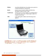
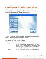
Page 95: ...utton and follow the onscreen instructions to continue and complete installation Drivers on the First Page Device Driver Ensures the full function of the following drivers Install this main driver before installing the other drivers Upon clicking this button the chipset VGA audio modem and LAN drivers would be installed one after the other Nvidia Installs the optional Nvidia VGA controller driver ...

Page 96: ...Hotfix Allows you to install the Microsoft hotfix for Windows XP Service Pack 2 only TouchScreen Allows you to use your fingers as a pointing device on the LCD screen See Touchscreen Utility for further instructions TPM Upon clicking this button the following screen appears TPM Support Security ...

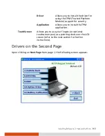
Page 97: ...plication Allows you to install the TPM application TouchScreen Allows you to use your fingers or optional touchscreen pen as a pointing device on the LCD screen refer to the next section for further instructions Drivers on the Second Page Upon clicking on Next Page from page 1 the following screen appears ...

Page 98: ...AV input port option USB to COM Allows you to use the optional wireless modem and GPS features to transmit information wirelessly MTCCTRL Allows you to use the built in heater feature that automatically turns on for low temperature hard disk drive operation OSD Installs the OSD on screen display utility that provides a graphic display to indicate the current status of certain operations ...

Page 99: ... USB WCDMA and Bluetooth devices WCDMA Allows you to install the Novatel EU740 Sierra 8775V WCDMA driver and application CDMA Allows you to install the Sierra 5720 25V CDMA driver and application Bluetooth Allows you to install the Bluetooth driver and application program for using the Bluetooth feature Smart Card Allows you to install the smart card driver for using the smart card reader feature ...

Page 100: ...wer ON OFF state during system startup Battery Calibration Upon clicking on this the following screen appears Utility Installs the battery pack automatic calibration utility that includes the Battery Monitor and Battery Learning programs Help Displays the instructions for performing a battery calibration ...

Page 101: ...ticular button and follow the onscreen instructions to continue and complete installation Drivers on the First Page Chipset Ensures the full function of the following drivers Install this main driver before installing the other drivers Upon clicking this button the chipset VGA modem and LAN drivers would be installed one after the other Nvidia Installs the optional Nvidia VGA controller driver ...

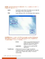
Page 102: ...appears TPM Support Security Driver Allows you to install the driver for using the TPM Trusted Platform Module support for security Application Allows you to install the TPM application TouchScreen Allows you to use your finger or optional touchscreen pen as a pointing device on the LCD screen See Touchscreen Utility for further instructions ...

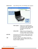
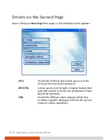
Page 103: ...screen appears Video Capture Allows you to install the video capture driver STK1160 to connect a video capture device through the AV input port option USB to COM Allows you to use the wireless modem and GPS features to transmit information wirelessly ...

Page 104: ...r that allows you to use the infrared function of the computer MTCCTRL Allows you to use the built in heater feature that automatically turns on for low temperature hard disk drive operation OSD Installs the OSD on screen display utility that provides a graphic display to indicate the current status of certain operations ...

Page 105: ...CDMA driver and application CDMA Install the Sierra 5720 25V CDMA driver and application Smart Card Installs the smart card driver for using the smart card reader feature Module Switch Allows you to power ON OFF the Bluetooth wireless feature WLAN radio as well as set the power ON OFF state during system startup ...

Page 106: ...the following screen Calibration appears Utility Installs the battery pack automatic calibration utility that includes the Battery Monitor and Battery Learning programs Help Displays the instructions for performing a battery calibration ...

Page 107: ...can use PenMount Monitor to configure your touchsreen 1 Cick the PenMount Monitor icon located on the system tray bring up the PenMount Control Panel 2 Click Standard Calibration 3 Click on the four sides points and the plus sign on the screen to calibrate your touchscreen for use on the computer ...

Page 108: ...Media Player etc to indicate the volume level The OSD disappears after a few seconds Fn F5 Fn F6 Icon appears on the screen to indicate the brightness level The OSD disappears after a few seconds Fn F7 F8 On Fn F7 F8 Off Icon appears on the screen to indicate that LCD backlight Fn F7 or display Fn F8 is on or off The OSD disappears after a few seconds Fn F9 LCD Fn F9 CRT Fn F9 Both Icon appears on...

Page 109: ...Icon Hot Key Button Operation OSD Description AC In AC Out Icon appears on the screen to indicate that AC power cord has been connected or unplugged The OSD disappears after a few seconds ...

Page 110: ......

Page 111: ... Computer Taking good care of your computer will ensure a trouble free operation and reduce the risk of damage to your computer This chapter gives you guidelines covering areas such as protecting storing cleaning and traveling ...

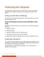
Page 112: ...ecurity Center alerts you to take action on the following security essentials Windows Firewall Windows Update Malware Protection anti virus anti spyware Others Internet security user account control For detailed information on Windows Security Center see Windows Help Using the Password The power on password protects your computer against unauthorized use If the password is set the prompt requestin...

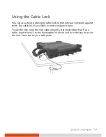
Page 113: ...ct your computer against theft The cable lock is available in most computer stores To use the lock loop the lock cable around a stationary object such as a table Insert the lock to the Kensington lock hole and turn the key to secure the lock Store the key in a safe place ...

Page 114: ...3 cm 5 inches away from electrical appliances that can generate a strong magnetic field such as a TV refrigerator motor or a large audio speaker Avoid moving the computer abruptly from a cold to a warm place A temperature difference of more than 10 C 18 F may cause condensation inside the unit which may damage the storage media Do not place the computer on an unsteady surface General Guidelines Do...

Page 115: ...attery pack is fully charged Doing so may avoid harm to the battery pack The battery pack is a consumable product and the following conditions will shorten its life when frequently charging the battery pack when using charging or storing the battery in high temperature condition To avoid hastening the deterioration of the battery pack thereby prolonging its useful life minimize the number of times...

Page 116: ...ter The computer s input voltage and surrounding temperature will directly affect the battery pack s charge and discharge time charging time will be prolonged when the computer is turned on To shorten the charging time it is recommended that you place the computer in sleep or hibernation mode a low temperature will prolong the charging time as well as hasten the discharge time Touchscreen Guidelin...

Page 117: ...t use excessive force on the display Avoid moving the computer while holding the display or twisting the display Avoid placing objects on top of the display as this may cause the glass to break thereby damaging the display Using the touchscreen during low temperature less than 5 o C may cause a slower response time this is normal A normal response time may be restored upon returning to room temper...

Page 118: ...se the AC adapter as the power source and as a battery charger Hand carry the computer Do not check it in as luggage If you need to leave the computer in the car put it in the trunk of the car to avoid exposing the computer to excessive heat When going through airport security it is recommended that you send the computer and flash disks through the X ray machine the device you set your bags on Avo...

Page 119: ...omputer problems can be caused by hardware software or both When you encounter any problem it might be a typical problem that can easily be solved This chapter tells you what actions to take when solving common computer problems ...

Page 120: ... cable connections are correct and secure Make sure that the configuration information is properly set in the BIOS Setup program Make sure that all the device drivers are correctly installed Make notes of your observations Are there any messages on the screen Do any indicators light Do you hear any beeps Detailed descriptions are useful to the service personnel when you need to consult one for ass...

Page 121: ...solve the problem See Initializing the Battery Pack in Chapter 3 for instructions The battery operating time indicated by the battery meter does not match the actual operating time The actual operating time can be different from the estimated time depending on how you are using the computer If the actual operating time is much less than the estimated time initialize the battery See Initializing th...

Page 122: ...s installed correctly During operation the screen may automatically turn off as a result of power management Press any key to see if the screen comes back The brightness level might be too low Increase brightness by pressing the Fn F6 hot key The display output might be set to an external device To switch the display back to the LCD press the Fn F9 hot key or change the display through the setting...

Page 123: ... or change the settings in Display Properties in Windows Hardware Device Problems The computer does not recognize a newly installed device The device may not be correctly configured in the BIOS Setup program Run the BIOS Setup program to identify the new type Make sure if any device driver needs to be installed Refer to the documentation that came with the device Make sure if the device needs any ...

Page 124: ...t the device connected is using an equivalent speed If you are printing to an infrared printer make sure that the appropriate driver is installed Make sure that the IrDA Fast Infrared Port is set to HP HSDL 2300 3600 Make sure that the IR port is set correctly in the BIOS Setup program If you are printing to an infrared printer make sure that the appropriate driver is installed If you are using an...

Page 125: ...The USB mouse does not work Make sure that the mouse cable is properly connected The touchpad does not work or the pointer is difficult to control with the touchpad Make sure that the touchpad is clean LAN Problems I cannot access the network Make sure that the LAN driver is correctly installed Make sure that the LAN cable is properly connected to the RJ 45 connector and the network hub Make sure ...

Page 126: ...nother WLAN device Make sure that the WLAN feature is turned on Fn F11 Make sure that the SSID setting is the same for every WLAN device in the network Your computer is not recognizing changes Restart the computer Make sure that the IP address or subnet mask setting is correct I cannot communicate with the computer in the network when Infrastructure mode is configured Make sure that the Access Poi...

Page 127: ...he modem does not work Make sure that the modem driver is correctly installed Make sure that the telephone line is properly connected Make sure that the COM port in the communication software is correctly set Turn off power management Optical Drive Problems The optical drive cannot read a disc Make sure that the disc is correctly seated in the tray with the label facing up Make sure that the disc ...

Page 128: ...tray 3 Pull the tray out until fully extended and then remove the disc PC Card Problems The PC card does not work Make sure that the PC card is correctly seated If the card requires an IRQ Interrupt ReQuest make sure that there is one available Or you can release another device IRQ in the BIOS Setup program The PC card stops communicating properly The application may have been reset when the compu...

Page 129: ...es not resume from Standby Sleep or Hibernation mode The computer automatically enters Standby Sleep or Hibernation mode when the battery pack is empty Do any one of the following Connect the AC adapter to the computer Replace the empty battery pack with a fully charged one The computer does not enter Hibernation mode with the Fn F10 hot keys Make sure that the Hibernation function is specified fo...

Page 130: ...e software program s documentation for further information If you are sure the operation has stop reset the computer See Resetting the Computer later in this chapter Sound Problems No sound is produced Make sure that the volume control is not set too low Make sure that the audio driver is correctly installed Make sure that the computer is not in Standby Sleep mode If using an external speaker make...

Page 131: ...external AC power make sure that the AC adapter is correctly and securely connected If so make sure that the electrical outlet works properly If you are using the battery power make sure that the battery is not discharged When you turn on the computer it stops after POST Restart your computer Other Problems The date time is incorrect Correct the date and time via the operating system or BIOS Setup...

Page 132: ... disk drive in use indicator if it flashes irregularly the program may be accessing data and preventing you from using the keyboard If you are sure the operation has stopped and you cannot use the restart function of the operating system reset the computer Reset the computer by any one of these methods Press Ctrl Alt Del on your built in keyboard If the above action does not work turn off the comp...

Page 133: ...d disk drive Easily removable for maintenance optional built in heater for low temperature support Optical drive option Easily swappable bay for slim type Combo DVD dual drive Audio Ports Two audio ports for Mic in Line out I O ports On right side X Bay two USB ports supports system boot up from optical drive IEEE 1394B or PS 2 port option On rear side IR port serial port RJ 11 port RJ 45 port par...

Page 134: ...ry Battery Li ion 3700 mAh 11 1 V option via optical drive bay Dimension W D H 12 9 10 7 1 81 inch 328 272 1 46 mm for 14 1 inch model 13 3 11 25 1 81 inch 338 286 46 mm for 15 inch model Weight Less than 9 25 lb 4 2 kg for 14 1 inch model Less than 9 7 lb 4 4 kg for 15 inch model Environment Temperature Operating 20 C 4 F to 55 C 131 F ...

Page 135: ...Appendix B Regulatory Information This appendix provides regulatory statements and safety notices on your computer ...

Page 136: ...ee that interference will not occur in a particular installation If this equipment does cause harmful interference to radio or television reception which can be determined by turning the equipment off and on the user is encouraged to try to correct the interference by one or more of the following measures Reorient or relocate the receiving antenna Increase the separation between the equipment and ...

Page 137: ...x appareils numériques de la classe B prescrites dans le Règlement sur le brouillage radioélectrique édicté par le ministère des Communications du Canada Safety Notices About the Battery Caution Texts Concerning Lithium Batteries DANISH ADVARSEL Lithiumbatteri Eksplosionsfare ved fejlagtig håndtering Udskiftning må kun ske med batteri af samme fabrikat og type Levér det brugte batteri tilbage til ...

Page 138: ...iquement avec une batterie du même type ou d un type équivalent recommandé par le constructeur Mettre au rebut les batteries usagées conformément aux instructions du fabricant Attention for USA Users The product that you have purchased contains a rechargeable battery The battery is recyclable At the end of its useful life under various state and local laws it may be illegal to dispose of this batt...

Page 139: ...locations unless the jack is specifically designed for wet locations Never touch non insulated telephone wires or terminals unless the telephone line has been disconnected at the network interface Use caution when installing or modifying telephone lines Avoid using the telephone function other than a cordless type during an electrical storm There may be a remote risk of electric shock from lightni...

Page 140: ...ts the Human Exposure limits found in OET Bulletin 65 2001 and ANSI IEEE C95 1 1992 Proper operation of this radio according to the instructions found in this manual will result in exposure substantially below the FCC s recommended limits The following safety precautions should be observed Do not touch or move antenna while the unit is transmitting or receiving Do not hold any component containing...

Page 141: ... Device Proximity Warning WARNING Do not operate a portable transmitter such as a wireless network device near unshielded blasting caps or in an explosive environment unless the device has been modified to be qualified for such use Antenna Warning WARNING To comply with the FCC and ANSI C95 1 RF exposure limits it is recommended that the antenna for this device be installed so as to provide a sepa...

Page 142: ...r in a particular commercial installation or if operated in a residential area If harmful interference with radio or television reception occurs when the device is turned on the user must correct the situation at the user s own expense The user is encouraged to try one or more of the following corrective measures Reorient or relocate the receiving antenna Increase the separation between the equipm...

Page 143: ...Union CE Marking and Compliance Notices Statements of Compliance English This product follows the provisions of the European Directive 1999 5 EC Danish Dette produkt er i overensstemmelse med det europæ iske direktiv 1999 5 EC Dutch Dit product is in navolging van de bepalingen van Europees Directief 1999 5 EC Finnish Tämä tuote noudattaa EU direktiivin 1999 5 EC määräyksiä French Ce produit est c...

Page 144: ...pecific countries or regions and is not allowed to be operated in countries or regions other than those of designated use As a user of these products you are responsible for ensuring that the products are used only in the countries or regions for which they were intended and for verifying that they are configured with the correct selection of frequency and channel for the country or region of use ...

Page 145: ...e device in areas places other than the 38 departments listed 01 Ain Orientales 36 Indre 66 Pyrénées 02 Aisne 37 Indre et Loire 67 Bas Rhin 03 Allier 41 Loir et Cher 68 Haut Rhin 05 Hautes Alpes 42 Loire 70 Haute Saône 08 Ardennes 45 Loiret 71 Saône et Loire 09 Ariège 50 Manche 75 Paris 11 Aude 55 Meuse 82 Tarn et Garonne 12 Aveyron 58 Nièvre 84 Vaucluse 16 Charente 59 Nord 88 Vosges 24 Dordogne 6...

Page 146: ...the wireless LAN radio off is not the same as disabling the wireless LAN card It is not necessary to disable the card to meet the regulatory requirements While operating the computer in those French departments that do not allow use of the wireless LAN equipment the user of the equipment must turn off the wireless LAN radio in order to comply with local regulations see Chapter 2 for more informati...

Reviews: