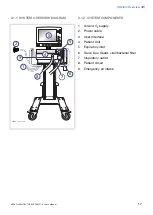
2.2.2 USER INTERFACE COMPONENTS
Refer to the User Interface Diagram for the
location of the following numbered
components:
1.
Current mode of ventilation
2.
Admit patient/Entered patient data and
admission date
3.
System status parameters
4.
Fixed keys
5.
Main Rotary Dial—used to select a menu
touchpad or parameter box, to adjust
values, and to confirm settings
6.
Special Function Keys—used to start
special ventilatory functions
7.
Direct Access Knobs—used for immediate
adjustment of breathing parameters
8.
AC Power indicator (green)
9.
Standby indicator (yellow)—when the
ventilator is in Standby, a flashing
message, Patient not ventilated, is
displayed on the screen directly above the
word Standby.
10. Start/Standby key
11. Luminescence detector—for automatically
adjusting screen brightness
12. Text messages, including patient
triggering symbols
13. Alarm messages
14. Waveform area—for monitoring two to
three individually scaled parameters,
including a volume/pressure loop and a
flow/volume loop
15. Measured values and alarm limits display
(customizable)
16. Additional settings
17. Additional measured values
18. Loudspeaker
19. Cable reel for the control cable
20. Slot for PC card with a cover
21. Control cable
22. Service connector
23. On/off switch
24. Locking lever for tilting
25. Model number
26. Serial number
27. Manufacturing information
SERVO-s VENTILATOR SYSTEM V7.0, User's Manual
19
|
System Overview
| 2 |
Summary of Contents for Maquet SERVO-s VENTILATOR SYSTEM V7.0
Page 1: ...x User s Manual SERVO s VENTILATOR SYSTEM V7 0 ...
Page 2: ......
Page 4: ...4 SERVO s VENTILATOR SYSTEM V7 0 User s Manual Infologic 1 64 2 1 TABLE OF CONTENTS ...
Page 14: ...14 SERVO s VENTILATOR SYSTEM V7 0 User s Manual 1 Introduction ...
Page 40: ...40 SERVO s VENTILATOR SYSTEM V7 0 User s Manual 3 Power supply ...
Page 66: ...66 SERVO s VENTILATOR SYSTEM V7 0 User s Manual 5 Monitor and record ...
Page 118: ...118 SERVO s VENTILATOR SYSTEM V7 0 User s Manual 6 Ventilation modes and functions ...
Page 162: ...162 SERVO s VENTILATOR SYSTEM V7 0 User s Manual 11 Technical data ...
Page 176: ...176 SERVO s VENTILATOR SYSTEM V7 0 User s Manual 13 Appendix User interface ...
Page 182: ...182 SERVO s VENTILATOR SYSTEM V7 0 User s Manual 15 Index ...
Page 183: ...x ...
Page 185: ...SERVO s VENTILATOR SYSTEM V7 0 User s Manual ...

