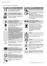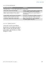
2.4.2 PATIENT UNIT SYMBOLS
Explanation
Symbol
CE label—indicates compliance with
the requirements of the Medical
Device Directive 93/42/EEC
CSA label—Indicates compliance
with Canadian and US standards
C US
PCT label - indicates compliance with
Russian standards
E 01
UDI Label - Unique Device
Identification. See technical
specifications, page 161.
Class I equipment, Type B—indicates
classification according to IEC
60601-1/EN 60601-1
Equipotentiality terminal
Note: The equipotentiality terminal
is designed for the connection of a
potential equalization conductor
according to DIN 42 801 and
EN/IEC 60601-1. The function of the
equipotentiality terminal is to equalize
potentials between the system and
other medical electrical devices that
can be touched simultaneously. The
equipotentiality terminal must not be
used for a protective earth
connection.
RS 232 / Serial port—connector for
data communication.
Note: This symbol may be different
depending on Patient Unit version.
User Interface connector
Note: This symbol may be different
depending on Patient Unit version.
10A Fuse for external DC power
supply.
External 12V DC input
Note: This symbol may be different
depending on Patient Unit version.
12V
+
-
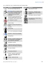
Expiratory label—gas flow from
patient.
Explanation
Symbol
Inspiratory label—gas flow to patient.
Gas exhaust port label—exhaust gas
flow from ventilator
Note: This port should not be
connected to a spirometer because
the volume through the exhaust port
is not equal to the expired volume
from the patient.
Alarm output connection
option—external alarm output
communication
Special waste
. This product
contains electronic and electrical
components. Discard disposable,
replaced and left-over parts in
accordance with appropriate
industrial and environmental
standards.
Caution
Consult Instructions for use
Batteries
+
-
Weight - Patient unit and User
interface.
Do not expose the battery to heat or
fire.
Do not expose the battery to
mechanical force.
Do not dismantle, open or shred the
battery.
30
SERVO-s VENTILATOR SYSTEM V7.0, User's Manual
| 2 |
System Overview
|
Summary of Contents for Maquet SERVO-s VENTILATOR SYSTEM V7.0
Page 1: ...x User s Manual SERVO s VENTILATOR SYSTEM V7 0 ...
Page 2: ......
Page 4: ...4 SERVO s VENTILATOR SYSTEM V7 0 User s Manual Infologic 1 64 2 1 TABLE OF CONTENTS ...
Page 14: ...14 SERVO s VENTILATOR SYSTEM V7 0 User s Manual 1 Introduction ...
Page 40: ...40 SERVO s VENTILATOR SYSTEM V7 0 User s Manual 3 Power supply ...
Page 66: ...66 SERVO s VENTILATOR SYSTEM V7 0 User s Manual 5 Monitor and record ...
Page 118: ...118 SERVO s VENTILATOR SYSTEM V7 0 User s Manual 6 Ventilation modes and functions ...
Page 162: ...162 SERVO s VENTILATOR SYSTEM V7 0 User s Manual 11 Technical data ...
Page 176: ...176 SERVO s VENTILATOR SYSTEM V7 0 User s Manual 13 Appendix User interface ...
Page 182: ...182 SERVO s VENTILATOR SYSTEM V7 0 User s Manual 15 Index ...
Page 183: ...x ...
Page 185: ...SERVO s VENTILATOR SYSTEM V7 0 User s Manual ...

