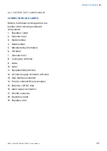
GAS FLOW THROUGH THE PATIENT UNIT
Refer to the Patient Unit gas flow diagram for
the location of the following numbered
components:
1.
Gas inlet for O
2
2.
Gas inlet for air
3.
The gas flow is regulated by the gas
modules for Air and O
2
.
4.
The gases are mixed in the inspiratory
mixing section
.
5.
The Oxygen concentration can be
measured with an O
2
cell or O
2
sensor.
An O
2
cell is shown here.
The O
2
cell is protected by a bacteria filter.
6.
The pressure of the mixed gas delivered
to the patient is measured by the
Inspiratory pressure transducer.
The transducer is protected by a bacterial
filter.
7.
The inspiratory channel delivers the mixed
gas to the patient systems inspiratory
tubing. The inspiratory channel also
contains a safety valve.
8.
The patient breathing systems expiratory
tubing is connected to the expiratory inlet.
The inlet also contains a moisture trap.
9.
The gas flow through the expiratory
channel is measured by ultrasonic
transducers.
10. The expiratory pressure is measured by
the expiratory pressure transducer
(located inside the ventilator). The
transducer is protected by a bacterial filter
inside the expiratory cassette.
11. The pressure (PEEP) in the patient system
is regulated by the expiratory valve.
12. Gas from the patient system leaves the
ventilator via the expiratory outlet. The
outlet contains a non-return valve.
Note: The expiratory cassette can be
exchanged between different SERVO-s and
SERVO-i Ventilator Systems. Always
perform a Pre-use check after exchanging
an expiratory cassette.
32
SERVO-s VENTILATOR SYSTEM V7.0, User's Manual
| 2 |
System Overview
|
Summary of Contents for Maquet SERVO-s VENTILATOR SYSTEM V7.0
Page 1: ...x User s Manual SERVO s VENTILATOR SYSTEM V7 0 ...
Page 2: ......
Page 4: ...4 SERVO s VENTILATOR SYSTEM V7 0 User s Manual Infologic 1 64 2 1 TABLE OF CONTENTS ...
Page 14: ...14 SERVO s VENTILATOR SYSTEM V7 0 User s Manual 1 Introduction ...
Page 40: ...40 SERVO s VENTILATOR SYSTEM V7 0 User s Manual 3 Power supply ...
Page 66: ...66 SERVO s VENTILATOR SYSTEM V7 0 User s Manual 5 Monitor and record ...
Page 118: ...118 SERVO s VENTILATOR SYSTEM V7 0 User s Manual 6 Ventilation modes and functions ...
Page 162: ...162 SERVO s VENTILATOR SYSTEM V7 0 User s Manual 11 Technical data ...
Page 176: ...176 SERVO s VENTILATOR SYSTEM V7 0 User s Manual 13 Appendix User interface ...
Page 182: ...182 SERVO s VENTILATOR SYSTEM V7 0 User s Manual 15 Index ...
Page 183: ...x ...
Page 185: ...SERVO s VENTILATOR SYSTEM V7 0 User s Manual ...


