6.2 IMPORTANT DEFINITIONS
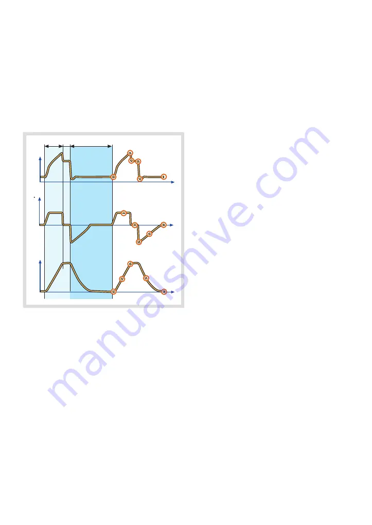
The graphic display of pressure, flow and
volume is visualized in waveforms. Modes of
ventilation directly affect flow, pressure and
volume patterns.
6.2.1 VOLUME CONTROL
P
1
2
3
4
5
6
t
t
8
10
11
12
13
14
15
16
t
V
V
x
y
z
I:E
9
7
X.
Inspiration time
Y.
Pause time
Z.
Expiration time
PRESSURE-TIME WAVEFORM
1.
Start of Inspiration
2.
Peak inspiratory pressure
3.
Early inspiratory pause pressure
4.
End inspiratory pause pressure
5.
Early expiratory pressure
6.
End expiratory pressure
FLOW-TIME WAVEFORM
7.
Peak inspiratory flow
8.
Zero flow phase
9.
Peak expiratory flow
10. Slope decelerating expiratory limb
11. End expiratory flow
VOLUME-TIME WAVEFORM
12. Start of inspiration
13. The slope represents current delivery of
inspiratory tidal volume
14. End inspiration
15. The slope represents current patient
delivery of expiratory tidal volume
16. End expiration
70
SERVO-s VENTILATOR SYSTEM V7.0, User's Manual
| 6 |
Ventilation, modes and functions
|
Summary of Contents for Maquet SERVO-s VENTILATOR SYSTEM V7.0
Page 1: ...x User s Manual SERVO s VENTILATOR SYSTEM V7 0 ...
Page 2: ......
Page 4: ...4 SERVO s VENTILATOR SYSTEM V7 0 User s Manual Infologic 1 64 2 1 TABLE OF CONTENTS ...
Page 14: ...14 SERVO s VENTILATOR SYSTEM V7 0 User s Manual 1 Introduction ...
Page 40: ...40 SERVO s VENTILATOR SYSTEM V7 0 User s Manual 3 Power supply ...
Page 66: ...66 SERVO s VENTILATOR SYSTEM V7 0 User s Manual 5 Monitor and record ...
Page 118: ...118 SERVO s VENTILATOR SYSTEM V7 0 User s Manual 6 Ventilation modes and functions ...
Page 162: ...162 SERVO s VENTILATOR SYSTEM V7 0 User s Manual 11 Technical data ...
Page 176: ...176 SERVO s VENTILATOR SYSTEM V7 0 User s Manual 13 Appendix User interface ...
Page 182: ...182 SERVO s VENTILATOR SYSTEM V7 0 User s Manual 15 Index ...
Page 183: ...x ...
Page 185: ...SERVO s VENTILATOR SYSTEM V7 0 User s Manual ...


