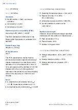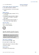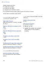
11.4 PATIENT CIRCUIT
The patient circuit configuration are intended
to provide the following range of inspired tidal
volume:
22 mm tubing, Tidal Volumes 100 - 2000 ml.
For information regarding patient circuit
configurations to be used with SERVO-s
Ventilator System, see System Flow Chart,
Ventilation, Patient Connection, part no. 66 92
522.
11.4.1 PATIENT CIRCUIT TEST
In the Pre-use check, the patient circuit is
tested to determine if it is within these
recommended ranges. If the tested parameters
are within the specified ranges, the
inaccuracies stated are maintained.
Inspiratory resistance: 0 - 8.5 cmH
2
O/l/s at
flow rate 60 l/min
Expiratory resistance: 0 - 8.5 cmH
2
O/l/s at
flow rate 60 l/min
Compliance: 0.5 - 5.0 ml/cmH
2
O at airway
pressure 50 cmH
2
O.
The limits used in the presentation under
Status>Patient Circuit are adjusted for
measurement inaccuracy.
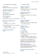
11.5 INSPIRATORY CHANNEL
Pressure drop
Maximum: 6 cmH
2
O at a flow of 60 l/min
Internal compressible factor
Maximum: 0.1 ml/cmH
2
O
Gas delivery system
Microprocessor controlled valves
Gas delivery device
Flow range:
0 - 3.3 l/s
Inaccuracy: ±(0.1 ml/s + 5 % of set value)
Maximum pressure setting
120 cmH
2
O
Inaccuracy: ±(1 cmH
2
O +5 % of set value)
Maximum airway pressure
125 cmH
2
O
NIV Max leakage compensation level
65 l/min
O
2
concentration
Setting range: 21 - 100%
Inaccuracy:
±
3 vol% O
2
Inspiratory Minute Volume
Setting range: 0.5 - 60 l/min
Inaccuracy ±(0.18 l/min + 7 % of set value)
4
Inspiratory Tidal Volume
Setting range: 100 - 2000 ml
Inaccuracy: ±(4 ml + 7 % of set volume)
4. at RR <45 b/min
148
SERVO-s VENTILATOR SYSTEM V7.0, User's Manual
| 11 |
Technical data
|
Summary of Contents for Maquet SERVO-s VENTILATOR SYSTEM V7.0
Page 1: ...x User s Manual SERVO s VENTILATOR SYSTEM V7 0 ...
Page 2: ......
Page 4: ...4 SERVO s VENTILATOR SYSTEM V7 0 User s Manual Infologic 1 64 2 1 TABLE OF CONTENTS ...
Page 14: ...14 SERVO s VENTILATOR SYSTEM V7 0 User s Manual 1 Introduction ...
Page 40: ...40 SERVO s VENTILATOR SYSTEM V7 0 User s Manual 3 Power supply ...
Page 66: ...66 SERVO s VENTILATOR SYSTEM V7 0 User s Manual 5 Monitor and record ...
Page 118: ...118 SERVO s VENTILATOR SYSTEM V7 0 User s Manual 6 Ventilation modes and functions ...
Page 162: ...162 SERVO s VENTILATOR SYSTEM V7 0 User s Manual 11 Technical data ...
Page 176: ...176 SERVO s VENTILATOR SYSTEM V7 0 User s Manual 13 Appendix User interface ...
Page 182: ...182 SERVO s VENTILATOR SYSTEM V7 0 User s Manual 15 Index ...
Page 183: ...x ...
Page 185: ...SERVO s VENTILATOR SYSTEM V7 0 User s Manual ...

