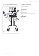
2.1 VENTILATOR
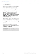
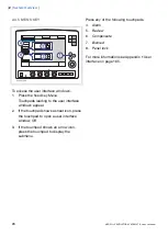
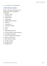
The User Interface is used to control ventilator
settings. Settings may be adjusted using
touchpads on the screen or a rotary dial.
Breathing parameters are continuously
measured and controlled. A difference
between the actual measured value of a
parameter and the preset or calculated value
results in the adjustment of gas delivery to
achieve the target value.
The system has two gas modules, one for air
and one for O
2
. Gases may be supplied by a
medical pipeline system, a compressor, or by
gas tanks.
Ensure that the ventilator is in its locked
position on the cart or holder used, to prevent
unintentional movements.
CAUTION: Lock the wheels if the ventilator
is not to be used for transportation.
16
SERVO-s VENTILATOR SYSTEM V7.0, User's Manual
| 2 |
System Overview
|
Summary of Contents for Maquet SERVO-s VENTILATOR SYSTEM V7.0
Page 1: ...x User s Manual SERVO s VENTILATOR SYSTEM V7 0 ...
Page 2: ......
Page 4: ...4 SERVO s VENTILATOR SYSTEM V7 0 User s Manual Infologic 1 64 2 1 TABLE OF CONTENTS ...
Page 14: ...14 SERVO s VENTILATOR SYSTEM V7 0 User s Manual 1 Introduction ...
Page 40: ...40 SERVO s VENTILATOR SYSTEM V7 0 User s Manual 3 Power supply ...
Page 66: ...66 SERVO s VENTILATOR SYSTEM V7 0 User s Manual 5 Monitor and record ...
Page 118: ...118 SERVO s VENTILATOR SYSTEM V7 0 User s Manual 6 Ventilation modes and functions ...
Page 162: ...162 SERVO s VENTILATOR SYSTEM V7 0 User s Manual 11 Technical data ...
Page 176: ...176 SERVO s VENTILATOR SYSTEM V7 0 User s Manual 13 Appendix User interface ...
Page 182: ...182 SERVO s VENTILATOR SYSTEM V7 0 User s Manual 15 Index ...
Page 183: ...x ...
Page 185: ...SERVO s VENTILATOR SYSTEM V7 0 User s Manual ...


