E
N
G
L
I
S
H
INSTALLATION INSTRUCTIONS
ASSEMBLY AND CABLING (only for GW 90 971)
INSTALLATION
Ensure that the system is powered down before performing any
operation.
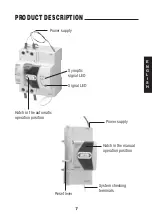
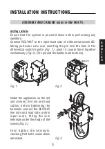
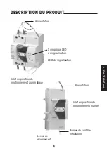
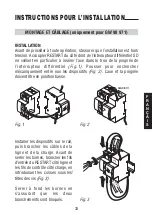
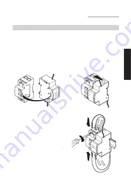
Connect RESTART to the right-hand side of differential switch SD,
taking particular care over inserting the pin into the hole in the
differential switch handle (Fig. 1); push to couple them together
mechanically (Fig. 2). (The pin and the handle must be down).
Install the appliances on the rail
and connect the line and load
cables; before tightening the
terminals connect the RESTART
line side and load side control
input wires, fitting the wire
terminals under the heads of the
screws (Fig. 3).
Fully tighten the terminals,
checking that both connections
are locked.
Fig. 1
Fig. 2
LIN
E
LOA
D
2
CLACK !!!
Fig. 3
21
Summary of Contents for RESTART RD GW 90 971
Page 1: ...RESTART RD Serie 90 GW 90 971...
Page 13: ...E N G L I S H Series 90 RESTART RD...
Page 25: ...F R A N A I S S rie 90 RESTART RD...
Page 37: ...E S P A O L Serie 90 RESTART RD...
Page 49: ...D E U T S C H Serie 90 RESTART RD...
Page 61: ...61 NOTE...
Page 62: ...62 NOTE...
Page 63: ......


