background image

I-ON

0-OFF

7

8

9

10

11

12

I-O

N

0-O

FF

1

ON

LED ON

R

7

8

9

10

11

12

I-O

N

0-O

FF

2

3

11

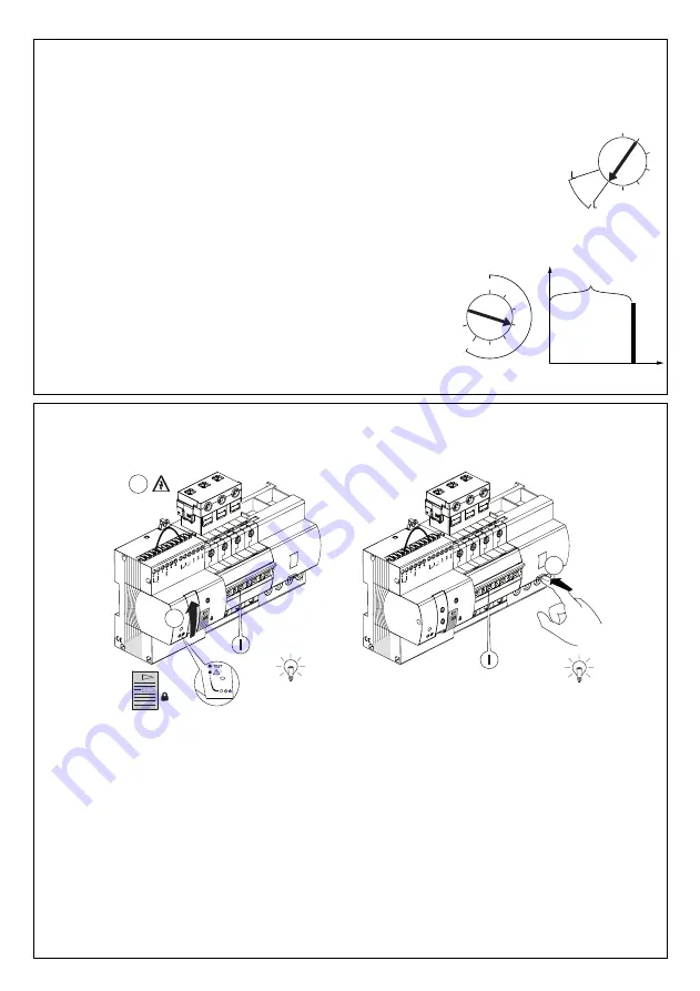
TEST DI RICHIUSURA AUTOMATICA CON VERIFICA PREVENTIVA DELL’IMPIANTO 

AUTOMATIC RESET TEST WITH PREVENTIVE

SYSTEM CHECK - 

TEST AUTOMATICKÉHO RESTARTU S PREVENTIVNÍ KONTROLOU OBVODU

Alla prima messa in servizio, far scattare l’interruttore premendo il tasto di test. Aspettare la richiusura automatica. Nel caso il ciclo di riarmo
non venga concluso correttamente verificare l’isolamento verso terra dell’impianto, che deve superare i 16 k

per I∆n 30mA, 5 k

per I∆n

300mA.

At the initial start-up, trigger the circuit breaker by pressing the test button key. Wait for the automatic reset. If the reset cycle is not completed correctly,
check the system's earthing insulation (which must exceed 16 kΩ per I∆n 30mA, 5kΩ per I∆n 300mA).

Při prvním zapojení do sítě, nechte chránič vypnout stisknutím testovacího tlačítka. Vyčkejte na automatický restart. Jestliže cyklus neproběhne správně,
zkontrolujte izolaci proti zemi, která musí být vyšší než 16 kΩ pro IΔn 30mA, 5kΩ pro IΔn 300mA.

RICHIUSURA AUTOMATICA CON VERIFICA PREVENTIVA DELL’IMPIANTO

AUTOMATIC RESET WITH PREVENTIVE SYSTEM CHECK -

AUTOMATICKÝ RESTART S PREVENTIVNÍ KONTROLOU OBVODU

Regolare il selettore R in base al valore di I∆n dell’interruttore differenziale accoppiato.

Adjust the selector R on the basis of the value of I∆n of the associated residual current circuit breaker.

Nastavte přepínač R na hodnotu IΔn připojeného proudového chrániče

OFF 1

5

2

3

10

R

CHECK 30mA

CHECK 300mA

CHECK 300mA = Idn 300/400mA

CHECK 30mA = Idn 30/100mA

Il selettore T permette di regolare il tempo che intercorre tra l’intervento dell’interruttore e la
verifica dell’impianto. L’impostazione 0’’ permette una verifica immediata.

The selector T allows you to adjust the time lapse between the tripping of the circuit breaker and the
system check. Set "0’’ to obtain an immediate check.

Přepínač T umožňuje nastavení času mezi intervencí přístroje a kontrolou obvodu. Čas "0" znamená
okamžité zahájení kontroly

0’’ 30’’

5’

1’

15’

30’

T

TRIP

CHECK

5 min

1h

i

T

Summary of Contents for RESTART RM TOP 90

Page 1: ...CH PŘÍSTROJŮ ACCOPPIAMENTO COUPLING SPOJOVÁNÍ RM TOP MTC 1 4P MT 1 4P MDC 2 4P MT BD 2 4P 4P 2P 3P 56mm 3 1P 27mm 2 1 L1 N L2 L3 NO L1 N L2 L3 OK 7 8 9 10 11 12 Negli accoppiamenti con interruttori 1P e 3P la maniglia motore in eccedenza deve essere tagliata Any excess motor handle after coupling with switches 1P and 3P must be cut off Při spojování s jističi 1P a 3P musí být rukojeť motor pohonu ...

Page 2: ...I ON 0 O FF 1 3 4 2 I ON 0 OFF I ON 0 O FF I ON 0 O FF TEST DI CORRETTO ACCOPPIAMENTO CORRECT COUPLING TEST TEST SPRÁVNÉHO PŘIPOJENÍ 2 ...

Page 3: ...1 2 3 4 3 Modulo di controllo del cortocircuito Short circuit detection module Modul kontroly zkratu INSTALLAZIONE INSTALLATION INSTALACE ...

Page 4: ...fferenziale If the circuit breaker is coupled with a residual current device the module cannot be directly installed on the output terminals of the residual current device V případě že k jističi bude připojen diferenciální blok modul nelze připojit přímo na výstupní svorky dif bloku 4 MT MDC MT BD L installazione di RM TOP accoppiato con MTC richiede la delocalizzazione del modulo di rilevamento d...

Page 5: ...ce k zamknutí 5 Connettere l alimentazione del dispositivo tra una fase e il neutro cavo nero fase cavo blu neutro Wire the device s power supply between one phase and neutral black cable phase blue cable neutral Připojit napájení zařízení mezi F a N F černý vodič N modrý vodič Nelle configurazioni trifase il neutro deve essere sempre collegato nell ultimo polo a sinistra dell interruttore In thre...

Page 6: ...6 7 8 9 10 11 12 8 230V OPEN CLOSE RESET 7 8 9 10 11 3 0 4 Nm 2 5 mm 7 8 9 10 11 12 0 4 Nm 2 5 mm 3 7 8 9 10 11 12 3 0 4 Nm 2 5 mm AUX1 AUX2 9 7 8 9 10 11 12 0 4 Nm 2 5 mm 3 ...

Page 7: ...orsetti non inclusi nel kit If there is not enough space to install the short circuiting detection module you can delocalise it on the DIN rail through terminals not supplied with the kit V případě že není dost místa k instalaci modulu kontroly zkratu je možné ho umístit na lištu DIN s pomocí svorek nejsou součástí KITu 7 8 9 10 11 12 p p p p N L1 L2 L3 ...

Page 8: ... N L1 2P 1P N 1 2 3 4 5 6 7 8 9 101112 L1 1 2 3 4 5 6 7 8 9 101112 N L1 N INSTALLAZIONE POSSIBILI CONFIGURAZIONI INSTALLATION POSSIBLE CONFIGURATIONS INSTALACE MOŽNÉ KONFIGURACE 8 L alimentazione deve essere sempre prelevata tra fase e neutro Isolare i cavi e i terminali non utilizzati The power supply must always be taken between phase and neutral Insulate the unused cables and terminals Napajení...

Page 9: ...uraci s kontrolou obvodu nebo bez kontroly 9 Comando a pulsanti Push button command Ovládání tlačítky Comando ciclico Cyclical command Cyklický příkaz Comando mantenuto Held command Příkaz přidržení L installazione di RM TOP accoppiato con MTC richiede la delocalizzazione del modulo di rilevamento del corto circuito The installation of the RM TOP coupled with the MTC requires the delocalisation of...

Page 10: ...nte Se l interruttore differenziale non interviene chiamare un tecnico per la verifica dell apparecchio N B The test must be carried out mon thly Call a technician to check the device if the residual current device does not trip Pozn Test se musí provádět měsíčně Pokud chránič neintervenuje zavolejte technika RM TOP OFF I ON 0 OFF 7 8 9 10 11 12 I O N 0 OFF 1 ON 2 3 7 8 9 10 11 12 I O N 0 OFF 4 Im...

Page 11: ...stliže cyklus neproběhne správně zkontrolujte izolaci proti zemi která musí být vyšší než 16 kΩ pro IΔn 30mA 5kΩ pro IΔn 300mA RICHIUSURA AUTOMATICA CON VERIFICA PREVENTIVA DELL IMPIANTO AUTOMATIC RESET WITH PREVENTIVE SYSTEM CHECK AUTOMATICKÝ RESTART S PREVENTIVNÍ KONTROLOU OBVODU Regolare il selettore R in base al valore di I n dell interruttore differenziale accoppiato Adjust the selector R on ...

Page 12: ...s This occurs when the device has detected a short circuit in the system or fol lowing four consecutive releases in 60 sec Červená LED trvale svítí stav blokace Tento stav nastane pokud restart detekuje zkrat v obvodu anebo dojde během 60s ke 4 po sobě následujícím výpadkům LED rosso semi intermittente il dispositivo ha misurato un basso livello di isolamento dell impianto e si pone in stato di at...

Page 13: ... automatica Use the selector T to set the time lapse between the tripping of the circuit breaker and the automatic reset Nastavte přepínač T na časový interval který má proběhnout mezi intervencí jističe a automatic restartem 0 30 5 1 15 30 T TRIP 1 RECLOSING 30 1h iT 30 X n 2 RECLOSING La selezione del tempo 욼T permette di impostare un intervallo di tempo crescente con l aumentare dei tentativi d...

Page 14: ...2 ON OFF OFF Contatto ausiliario configurato per segnalazione di scattato relè Auxiliary contact configured to indicate shunt trip release Pomocný kontakt pro signalizaci vypnutí relé LEGENDA KEY LEGENDA LED lampeggiante LED blinking LED bliká LED semi intermittente LED semi intermittent LED svítí přerušovaně LED fisso LED fixed LED svítí trvale ...

Page 15: ...us Zablokováno RESTART ON Aux contact 1 Aux contact 2 ON OFF OFF ON OFF ON OFF ON OFF Posizione selettori errata Correggere la posizione e premere il tasto R Incorrect selector position Correct the position and press key R Nesprávná volba přepínačů Upravte volbu a stiskněte tlačítko R Contatto ausiliario configurato per segnalazione di scattato relè Auxiliary contact configured to indicate shunt t...

Page 16: ...azaci červené LED manuálním sepnutím jističe nebo příkazem RESET vzdálené kontroly IN CASO DI LED ROSSO E VERDE LAMPEGGIANTI IF THE RED AND GREEN LEDS ARE BLINKING POKUD ČERVENÁ LED BLIKÁ I selettori R o T sono regolati in modo errato su valori non esistenti in posizione intermedia tra un valore di selezione e l altro Correggere la regolazione The R or T selector is incorrectly set on a non existe...

Page 17: ...tch between the different modes is confirmed when the left red LED blinks Pomocný kontakt je možné nastavit tisknutím tlačítka R alespoň po dobu 5s a jeho následným uvolněním Přechod mezi modalitami je potvrzen bliknutími červené LED vlevo Un lampeggio LED rosso One red LED flash Červená LED dioda blikne jednou NO Default Tre lampeggi LED rosso Three red LED flashes Červená LED dioda blikne třikrá...

Page 18: ...FIGURAZIONE CONTATTO AUX2 AUX2 CONTACT SETUP NASTAVENÍ KONTAKTU AUX2 Segnalazione di scattato relè Fault signalling Signalizace vypnutí relé závada Segnalazione aperto chiuso Open closed signalling Signalizace rozepnuto sepnuto 18 ...

Page 19: ...nce to ground Operating Rd0 16kΩ IΔn30 5kΩ IΔn300 Non operating Rd 8kΩ IΔn30 2 5kΩ IΔn300 Rated resistance between the live parts Operating Rcc0 1 8Ω Non operating Rcc 0 3Ω Maximum number of reset operations without test 10 Reset delay adjustment 0 1h Time of reclosing 3s 10s with test Remote opening time 2s Width 4 Modules Operating temperature from 5 C to 40 C IP20 Auxiliary contact AUX1 5 230Va...

Page 20: ...missione del prodotto sul mercato Comunitario è According to article 9 paragraph 2 of the European Directive 2004 108 EC and to article R2 paragraph 6 of the Decision 768 2008 EC the responsible for placing the apparatus on the Community market is GEWISS S p A Via A Volta 1 24069 Cenate Sotto BG Italy Tel 39 035 946 111 Fax 39 035 945 270 E mail qualitymarks gewiss com 39 035 946 111 8 30 12 30 14...

Reviews: