IQ lock AUT, EL / EL DL, EM / EM DL, C / C DL, M / M DL
19
Electrical connection
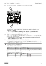
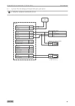
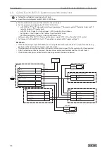
Cable and cover monitoring MST 210
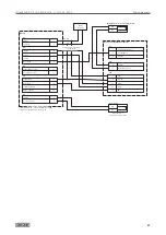
Terminal X10.22 is connected with terminal X8.25 to use sabotage monitoring (comprising cable and cover
monitoring). The sabotage monitoring signal is then tapped via terminals X10.23 and X8.24. The circuit is opened
in the event of a fault (cover open or cable fault).
Cover monitoring/cable monitoring
24
X8
25
23
X10
22
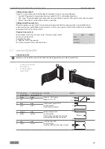
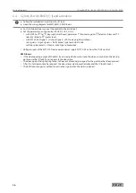
5.2 Rod drive IQ AUT
5.2.1 Connections
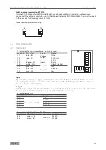
X1 - connection for power supply device, inputs and outputs
Connection
Wire colour
Signal
Function
X1.1
blue – BU
Voltage
supply
GND in
X1.3
red – RD
24 V (DC in)
X1.2
–
–
24 V DC
X1.5
brown – BN
Input
Release
X1.20
white – WH
Output 1
Output 1 (locked)
X1.21
grey – GY
Com
X1.22
pink – PK
Output 2
Unlocked
X1.21
grey – GY
Com
22
21
20
42
41
X1
X5
X4
5
2
3
1
41
42
43
2
1
Input
A potential-free contact (normally opened contact) must be connected to pins X1.2 and X1.5. If the contact is
actuated, IQ AUT moves to the unlocked position where it remains for the hold-open time. The time starts once
the contact has been disconnected.
Output
IQ AUT has two outputs with the potential which is connected to pin X1.21. The output “unlocked” is closed when
the drive rod is in the unlocked position. Output 1 can be set (see Service menu).
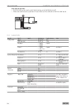
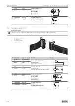
X4 - connection for ST220
Connection Signal
Function
X4.1
Connection for ST220
GND
X4.2
24V DC
X4.42
RS485-A
X4.41
RS485-B
X4.43
–
X5 - connection for GEZE-BUS (e.g.: IO 320)
Connection
Wire colour
Signal
Function
X5.42
yellow – YE
GEZE-BUS
RS485-A
X5.41
green – GN
RS485-B
Summary of Contents for IQ lock AUT
Page 56: ...IQ lock AUT EL EL DL EM EM DL C C DL M M DL 56 Wiring diagrams ...
Page 66: ...IQ lock AUT EL EL DL EM EM DL C C DL M M DL 66 Annex ...
Page 68: ...IQ lock AUT EL EL DL EM EM DL C C DL M M DL 68 Annex ...
Page 70: ...IQ lock AUT EL EL DL EM EM DL C C DL M M DL 70 Annex ...
Page 71: ...IQ lock AUT EL EL DL EM EM DL C C DL M M DL 71 Annex ...


