IQ lock AUT, EL / EL DL, EM / EM DL, C / C DL, M / M DL
36
Wiring diagrams
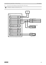
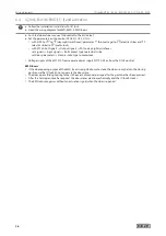
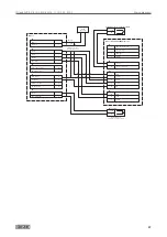
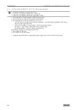
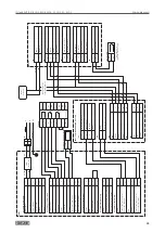
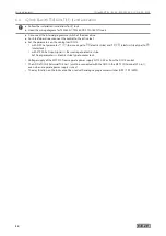
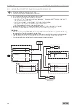
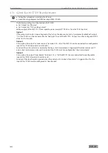
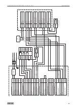
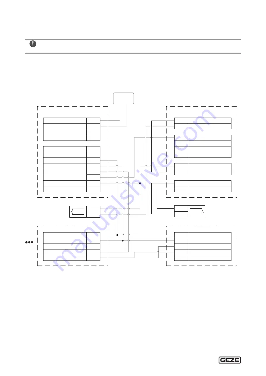
6.10 IQ lock EL with smoke switch control unit (RSZ 6)
X
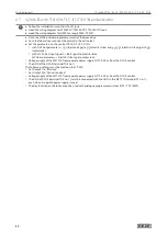
Follow the installation instructions for IQ lock.
X
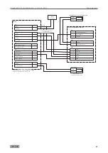
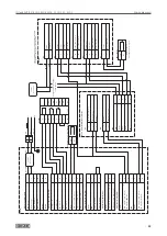
Heed the wiring diagram for the smoke switch control unit RSZ 6.
X
Remove the red jumper from the smoke switch control unit (RSZ 6).
X
Set the jumper J1 on the MST 210 to 2/3.
X
Set the jumper on the smoke switch (RS 5) to 1/2.
X
Press the reset button for commissioning.
X
After release by the smoke switch control unit (RSZ 6) or the smoke switch (RS 5), press the reset button.
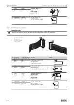
GND in
2
24 V DC
MRB / Manual trigger switch
5
6
KL2
RSZ6
24 V DC in
1
KL1
HOD / Hold-open device
4
GND
3
24 V DC
GND
7
8
AS / Ceiling-mounted detector
NC Alarm
9
10
COM Alarm
11
NO Alarm
12
24 V DC
NT 19.2-24
RD
BK / RD
COM
NO
24 V DC in
3
24 V DC
Release
24 V DC
Day / Night
2
5
2
4
COM Smoke detector
NC Smoke detector
8
9
X6
X4
MST 210
GND in
1
X7
24 V DC
Door contact (IN)
2
6
X5
GND in
2
9
RS5
24 V DC in
1
8
6
J P 1
Reset - Push button
COM
NO
Door contact
GND in
2
9
RS5
24 V DC in
1
8
6
J P 1
1 2 3
J P 1
1
2
3
When the door is closed
the contact is closed
Summary of Contents for IQ lock AUT
Page 56: ...IQ lock AUT EL EL DL EM EM DL C C DL M M DL 56 Wiring diagrams ...
Page 66: ...IQ lock AUT EL EL DL EM EM DL C C DL M M DL 66 Annex ...
Page 68: ...IQ lock AUT EL EL DL EM EM DL C C DL M M DL 68 Annex ...
Page 70: ...IQ lock AUT EL EL DL EM EM DL C C DL M M DL 70 Annex ...
Page 71: ...IQ lock AUT EL EL DL EM EM DL C C DL M M DL 71 Annex ...

