IQ lock AUT, EL / EL DL, EM / EM DL, C / C DL, M / M DL
54
Wiring diagrams
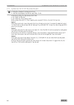
6.20 IQ lock AUT with Powerturn IS
X
Follow the mechanical installation instructions for IQ lock AUT.
X
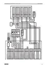
Heed the Powerturn wiring diagram.
Parameters DCU8xx
à
Set configurable output 1 to day/night changeover:
à
DPS: Set
a1
to
1 8
(“Day/Night” mode of operation message).
à
ST220: Set “PA1 function” to “Day/Night changeover”.
à
Set bar message contact type to electric strike contact:
à
DPS:
Set
®®
to
0 2
(electric strike).
à
ST220: Set the “Signals”, “Input signals”, “Bolt contact type”, “Bolt contact type” to “NC”.
à
Set the electric strike type to motor lock:
à
DPS: Set
TO
to
0 3
.
à
ST220: Set “Door parameters” “Electric strike type” to “Motor lock”.
Voltage supply
à
Take the voltage supply MST 210 from a separate power supply or from the DCU8xx control.
à
Take the voltage supply rod drive (IQ AUT) from a separate power supply.
Abbreviation in illustration on page
Component
BGS
Opposite hinge side
BS
Hinge side
DPS
Display programme switch
IQ AUT
Rod drive
IQ lock EL (DL)
Self-locking motor lock with panic function (2-leaf)
KÜ
Cable transition
MST 210
Motor lock control
NT
Power supply
Key switch xxx
Key switch
TK
Door contact
Cable recommendation
No.
Cable
1
NYM-J 3x 1.5
2
J-Y (ST)Y 2×2×0.6
3
J-Y (ST)Y 3×2×0.6
4
J-Y (ST)Y 4×2×0.6
9
Empty pipe inner diameter 10 mm
10
Supplied by GEZE:
à
IQ lock XX
10 m
LiYY 12×0.14 mm²
à
IQ AUT
10 m
LiYY 8×0.34 mm²
à
TK (ID:106133)
6 m
LiYY 4×0.14 mm²
à
K600
5 m
FRNC-LSIHSI FE90
on-site
Summary of Contents for IQ lock AUT
Page 56: ...IQ lock AUT EL EL DL EM EM DL C C DL M M DL 56 Wiring diagrams ...
Page 66: ...IQ lock AUT EL EL DL EM EM DL C C DL M M DL 66 Annex ...
Page 68: ...IQ lock AUT EL EL DL EM EM DL C C DL M M DL 68 Annex ...
Page 70: ...IQ lock AUT EL EL DL EM EM DL C C DL M M DL 70 Annex ...
Page 71: ...IQ lock AUT EL EL DL EM EM DL C C DL M M DL 71 Annex ...


