IQ lock AUT, EL / EL DL, EM / EM DL, C / C DL, M / M DL
40
Wiring diagrams
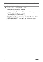
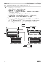
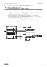
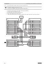
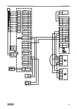
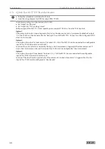
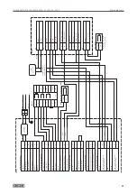
6.13 IQ lock EL with TZ 320 SN and activation
X
Follow the installation instructions for IQ lock.
X
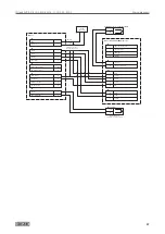
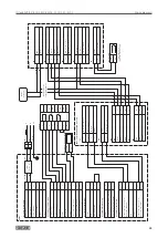
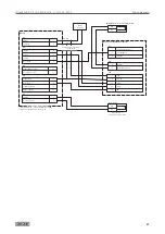
Heed the wiring diagram for GEZE SecuLogic RWS (TZ 320).
The following settings must be made on the TZ 320:
X
Set Output 1 to “BA drive”.
X
Set Output 2 to “TOE working current”
Voltage supply of the MST 210 is from separate power supply NT 19.2-24 or from the TZ 320 control
Option 1
If the motor lock is to be in operating mode “day” when the door control unit is “permanently unlocked”, output
“1” of the TZ 320 must be connected to the “day/night” input of the MST 210. Output 1 must be configured to “BA
drive” for this function.
Option 2
As an option, the output “cylinder contact” (terminals 24 + 25) of the MST 210 can be connected to a configurable
input of the TZ 320 (terminals 2 and 52 or 53).
Function: When the cylinder is actuated by the key, a short-term release is triggered at the door control unit. If
only a short-term release is desired, the input of the TZ 320 must be configured to “short-term release”.
Option 3
As an option, the output “door handle” (terminals 16 + 17) of the MST 210 can be connected to a configurable
input of the TST320 (terminals 2 and 52 or 53).
Function: If the door handle is pressed when the control unit is locked, a “pre-alarm” is triggered. For this, the
input of the TZ 320 must be configured to “door handle”.
Summary of Contents for IQ lock AUT
Page 56: ...IQ lock AUT EL EL DL EM EM DL C C DL M M DL 56 Wiring diagrams ...
Page 66: ...IQ lock AUT EL EL DL EM EM DL C C DL M M DL 66 Annex ...
Page 68: ...IQ lock AUT EL EL DL EM EM DL C C DL M M DL 68 Annex ...
Page 70: ...IQ lock AUT EL EL DL EM EM DL C C DL M M DL 70 Annex ...
Page 71: ...IQ lock AUT EL EL DL EM EM DL C C DL M M DL 71 Annex ...

