IQ lock AUT, EL / EL DL, EM / EM DL, C / C DL, M / M DL
50
Wiring diagrams
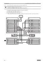
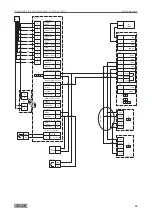
6.18 IQ lock AUT with EMD (-F, -I) and activation
X
Follow the mechanical installation instructions for IQ lock.
X
Heed the wiring diagram for EMD, EMD-F, EMD Invers.
X
For 2-leaf door drives connect the control to the active leaf.
X
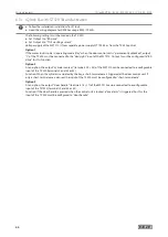
Set the parameters on the control DCU2, DCU2-F, DCU-I as follows:
With DPS:
à
Set
A1
to
18
(day and night switchover),
parameter
rr
(bar message) to
02
(electric strike) and
to
(electric strike) to
03
(motor lock).
With ST220:
à
Set Signals
Output signals
PA1 to day/night switchover.
à
Set Signals
Input signals
Bolt contact type to electric strike.
à
Set Door parameters
Electric strike type to motor lock.
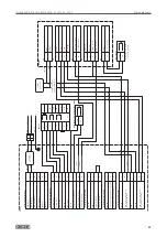
Voltage supply of the MST 210 from separate power supply NT 19.2-24 or from the DCU2 control.
Voltage supply of the rod drive IQ AUT from separate 24 V DC 1.5 A power supply.
EMD Invers:
à
If the door opening output of the EMD-Invers is configured to motor damage, the door is only held in the
closing position via the IQ lock EL, no longer via the door drive.
à
The door opens through spring force in the event of manual passage after the panic bar has been pressed.
à
After the hold-open time has expired, the door closes electromechanically and the IQ locks EL lock.
à
The EMD also recognises without an actuation signal when the door is opened.
Summary of Contents for IQ lock AUT
Page 56: ...IQ lock AUT EL EL DL EM EM DL C C DL M M DL 56 Wiring diagrams ...
Page 66: ...IQ lock AUT EL EL DL EM EM DL C C DL M M DL 66 Annex ...
Page 68: ...IQ lock AUT EL EL DL EM EM DL C C DL M M DL 68 Annex ...
Page 70: ...IQ lock AUT EL EL DL EM EM DL C C DL M M DL 70 Annex ...
Page 71: ...IQ lock AUT EL EL DL EM EM DL C C DL M M DL 71 Annex ...

