background image


Pos: null /BA_Module/BA_GA  Mechanische Montage/BAGA006603_M001 @ 0\mod_1273581431158_28.docx @ 528695 @ 1 @ 1 


3


Mechanical installation 

Prerequisites 

The permissible loads on walls, fastenings, mountings and transmission elements must not 
be exceeded, even for maximum holding torques or locking torques (▶ refer to technical 
data). 
 
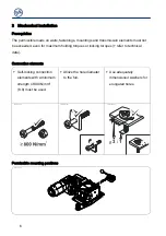
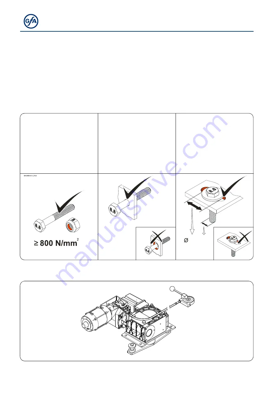
Connection elements 


Self-locking connection 
elements with a minimum 
strength of 800 N/mm

2


(8.8) must be used. 


Utilize the hole diameter 
to the full. 


Use adequately 
dimensioned washers for 
elongated holes. 

BAGAB00002_Z002

BAGAB00003_Z002

3 : 1

 
Permissible mounting positions 

BAGAC06401_Z001


Summary of Contents for 10003232 00011

Page 1: ...Deckblatt BAAA000001_M003 17 mod_1444211755814_28 docx 891110 1 Installation Instructions ELEKTROMAT FT 80 2 45 00 Model 10003232 00011 en Status 06 03 2020 Pos null BA_Module BA_Seitenumbruch 0 mod_...

Page 2: ...BACA000001_M002 15 mod_1416821436083_28 docx 864410 1 GfA ELEKTROMATEN GmbH Co KG Wiesenstra e 81 D 40549 D sseldorf www gfa elektromaten de info gfa elektromaten de Pos null BA_Module BA_Seitenumbru...

Page 3: ...on 12 8 Limit switch connection 13 9 Emergency manual operation lever 14 10 Completing commissioning inspection 15 11 Declaration of incorporation Declaration of conformity 16 Pos null BA_Module BA_Se...

Page 4: ...ation shall be rendered null and void Safety information Installation and initial operation tasks are to be performed by trained skilled fitters only Only trained electrical craftsmen are permitted to...

Page 5: ...per hour 20 h 1 Class of protection IP 65 Limit switch range maximum revolutions of output shaft hollow shaft 1 Temperature range 10 40 60 C Pos null BA_Module BA_FC Temperaturbereich BAFC000001_M002...

Page 6: ...ansmission elements must not be exceeded even for maximum holding torques or locking torques refer to technical data Connection elements Self locking connection elements with a minimum strength of 800...

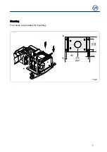
Page 7: ...7 Mounting Four holes are provided for mounting...

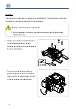
Page 8: ...fficient load carrying capacity Tighten all connection elements M12 to 75 Nm Install all other connection elements according to the specifications of the door manufacturer BAGAE06401_Z001 75 Nm 8 8 8...

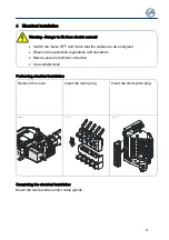
Page 9: ...e cables are de energised Observe the applicable regulations and standards Make a proper electrical connection Use suitable tools Performing electrical installation Remove the cover Insert the motor p...

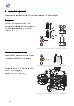
Page 10: ...positions for OPEN and CLOSE Prerequisite The door must open when the OPEN pushbutton is operated If the door closes L1 and L2 must exchanged with the current switched off Adjusting the OPEN limit po...

Page 11: ...e OPEN final limit position presets the OPEN SAFETY limit switch The door must stop safely if the direction of rotation is wrong or the OPEN limit switch S3 fails If necessary carry out fine adjustmen...

Page 12: ...x 570 1 1 6 Motor connection M1 Motor X13 Motor plug Pos null BA_Module BA_MC Alternativer Motoranschluss BAMC011001_M001 0 mod_1271681105421_28 docx 518476 1 1 7 Alternative motor connection M1 Motor...

Page 13: ...5 26 27 28 S2 S1 X12 S6 S3 S4 S5 5 6 4 10 14 15 16 9 17 8 7 13 12 11 S9 F10 F10 Thermal contact S9 Release switch X12 Limit switch board S1 Safety open limit switch S2 Safety close limit switch S3 Ope...

Page 14: ...a means of opening or closing doors that do not have electric power supply Operation interrupts the control voltage Electrical operation is no longer possible Warning Injury through improper operatio...

Page 15: ...mounts screws locking rings etc are secure and in proper condition Electrical wiring Check the connection cables and cabling for damage or crushing Check that the screw connections and plug connectio...

Page 16: ...in which it has been installed complies with the provisions of the above mentioned directives Authorised representative to compile the technical documents is the undersigned D sseldorf 10 08 2018 Ste...

Reviews: