9
Pos: null /BA_Module/BA_HA Elektrische Montage/BAHA040101_M001 @ 0\mod_1222157034316_28.docx @ 83294 @ 1 @ 1
4
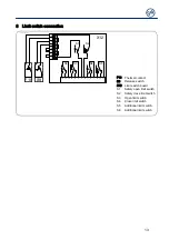
Electrical installation
Warning - Danger to life from electric current!
Switch the mains OFF and check that the cables are de-energised
Observe the applicable regulations and standards
Make a proper electrical connection
Use suitable tools
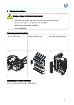
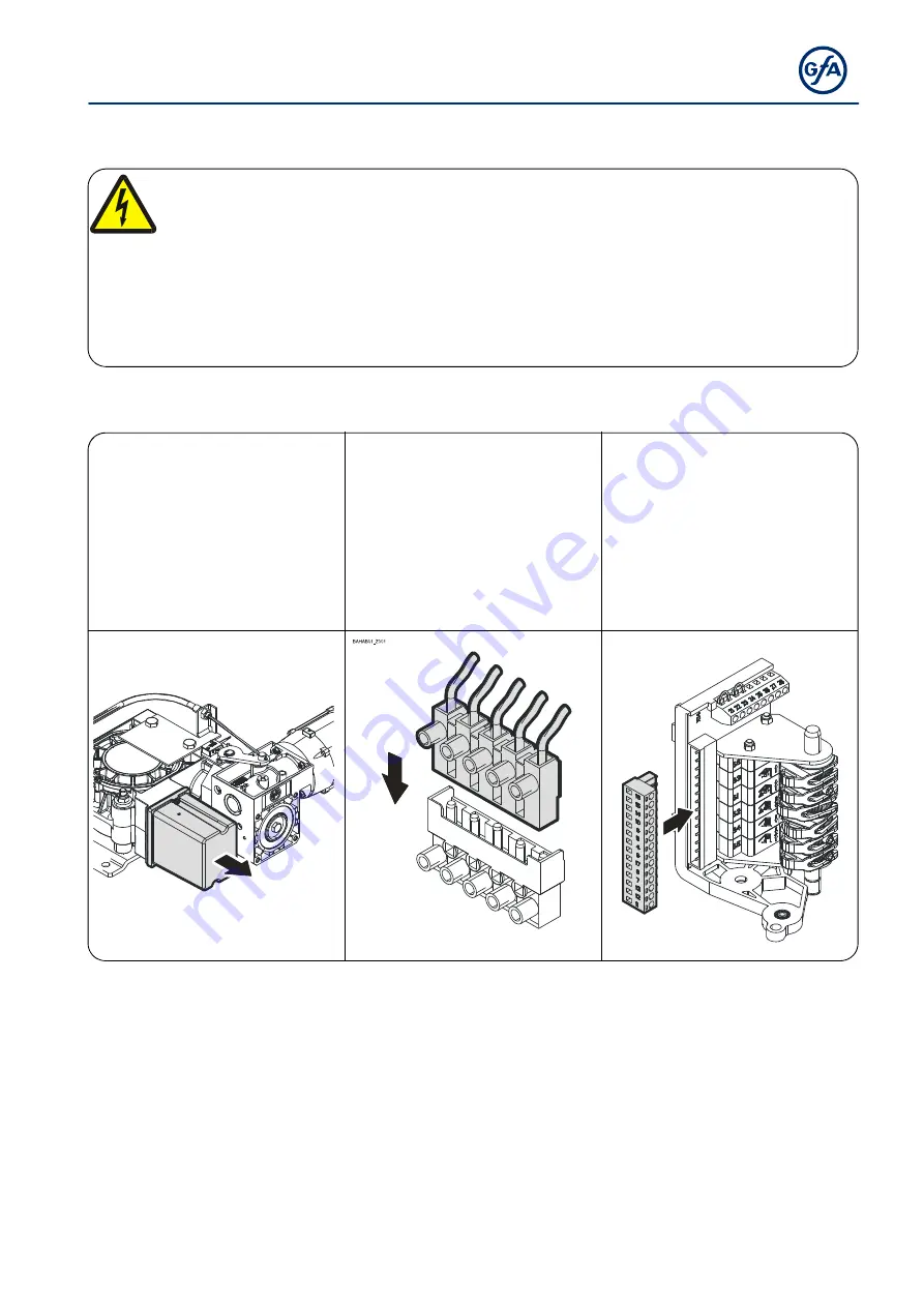
Performing electrical installation
Remove the cover.
Insert the motor plug.
Insert the limit switch plug.
BAHAA04_Z001
BAHAC01_Z001
Completing the electrical installation
Mount the cable entries and/or cable glands.
Pos: null /BA_Module/BA_Seitenumbruch @ 0\mod_1190719383361_0.docx @ 550 @ @ 1


