background image


1


General safety information 

 
Specified use 
The drive unit is intended for vertically moving doors that need to be secured against 
dropping. A safety brake is integrated into the gearbox. The drive unit must be mounted 
directly on the shaft of the door.  


The drive unit must be protected against moisture and aggressive environmental 
conditions (such as corrosive substances). The drive units are only suitable for indoor use. 
Appropriate protective measures must be taken for outdoor installation. The drive unit is 
not intended for hazardous areas. The values specified in the technical data of the drive 
unit must not be exceeded. The safe operation can only be ensured if used as specified.  


Target audience of these installation instructions 
These installation instructions are geared towards qualified persons trained in the handling 
of door systems. Expert knowledge, relevant skills and practical experience are what set 
apart qualified persons. They are capable of safely carrying out the tasks involving 
installation, maintenance and modernisation according to the instructions. 


Safe operation 

The safe operation of the product can only be ensured if it is used as specified. Follow the 
installation instructions. Observe all specifications, especially warnings, when installing the 
product in the overall system. GfA is not liable for damage resulting from non-observance 
of the installation instructions. The resulting overall system must be reassessed for its 
safety in accordance with applicable standards and directives (e.g. CE marking). These 
installation instructions refer only to a part of the overall system and are not sufficient as 
the sole instructions for the overall system. The installer of the system must prepare the 
instructions for the overall system.  
We recommend entering the danger area of the system only when the drive unit is at a 
standstill. 


Summary of Contents for 10004000 10011

Page 1: ...f Installation Instructions ELEKTROMAT SIK 25 10 WS 30 00 Model 10004000 10011 en Status 26 03 2021...

Page 2: ...2 GfA ELEKTROMATEN GmbH Co KG Wiesenstra e 81 D 40549 D sseldorf www gfa elektromaten de info gfa elektromaten de...

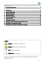
Page 3: ...switch connection 14 9 Emergency manual operation emergency hand crank 15 10 Completion of commissioning testing 17 11 Declaration of incorporation Declaration of conformity 19 Symbols Warning Potenti...

Page 4: ...ng of door systems Expert knowledge relevant skills and practical experience are what set apart qualified persons They are capable of safely carrying out the tasks involving installation maintenance a...

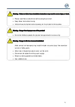
Page 5: ...third parties Warning Danger from improper use of the product Do not let children operate the product unsupervised or use as a toy Warning Danger to life from incorrect installation Work carried out i...

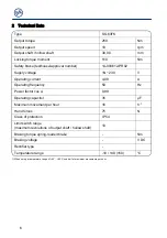
Page 6: ...g current 4 00 A Operating frequency 50 Hz Power factor cos 0 99 Operating capacitor 35 F Maximum movement per hour 16 h 1 Hand forces 75 N Class of protection IP 54 Limit switch range maximum revolut...

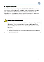
Page 7: ...cking torque and the approval number of the safety brake are available in the technical data of these instructions Warning Danger of the door dropping If you need to apply more than the permissible fo...

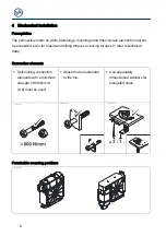
Page 8: ...maximum holding torques or locking torques refer to technical data Connection elements Self locking connection elements with a minimum strength of 800 N mm2 8 8 must be used Utilize the hole diameter...

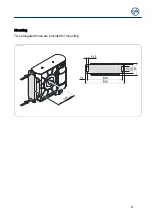
Page 9: ...9 Mounting Two elongated holes are provided for mounting BAGAD05001_Z001...

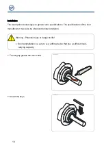
Page 10: ...ons of the door manufacturer must also be observed during installation Warning Potential injury or danger to life During installation be sure to use a lifting device that has a sufficient load carryin...

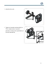
Page 11: ...tach the drive unit BAGAE05003_Z001 Tighten all connection elements M12 to 75 Nm Install all other connection elements according to the specifications of the door manufacturer BAGAE05004_Z001 75 Nm 8...

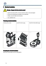
Page 12: ...energised Observe the applicable regulations and standards Make a proper electrical connection Use suitable tools Performing electrical installation Remove the cover Insert the motor plug Insert the...

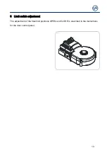
Page 13: ...13 6 Limit switch adjustment The adjustment of the final limit positions OPEN and CLOSE is described in the instructions for the door control panel...

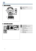
Page 14: ...ting capacitor M1 Motor X13 Motor plug 8 Limit switch connection F10 Thermal contact S10 Emergency manual operation X12 DES connection 1 Safety circuit 2 Channel B RS485 3 Ground 4 Channel A RS485 5 S...

Page 15: ...the emergency manual operation must be carried out against the closed brake Warning Danger of the door dropping If you need to apply more than the permissible force of 390N according to DIN EN 12604 D...

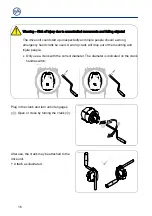
Page 16: ...and crank be used A wrong crank will drop out of the mounting and injure people Only use a crank with the correct diameter The diameter is indicated on the crank handle switch 1 2 m m 1 0 m m BAUA0001...

Page 17: ...g The gearbox stalls Releasing the stalling may cause the door to drop Block the door for pedestrians and vehicles Do not release the stalling Do not use the emergency manual operation Secure the door...

Page 18: ...al limit positions Limit switches Check the final limit positions by opening and closing the door completely The safety zone must not be reached Entire drive unit Note Have the drive checked annually...

Page 19: ...d complies with the provisions of the above mentioned directives Authorised representative to compile the technical documents is the undersigned D sseldorf 10 08 2018 Stephan Kleine CEO Signature The...

Page 20: ...20...

Reviews: