Gfp 663TH
April 2021
29
5.
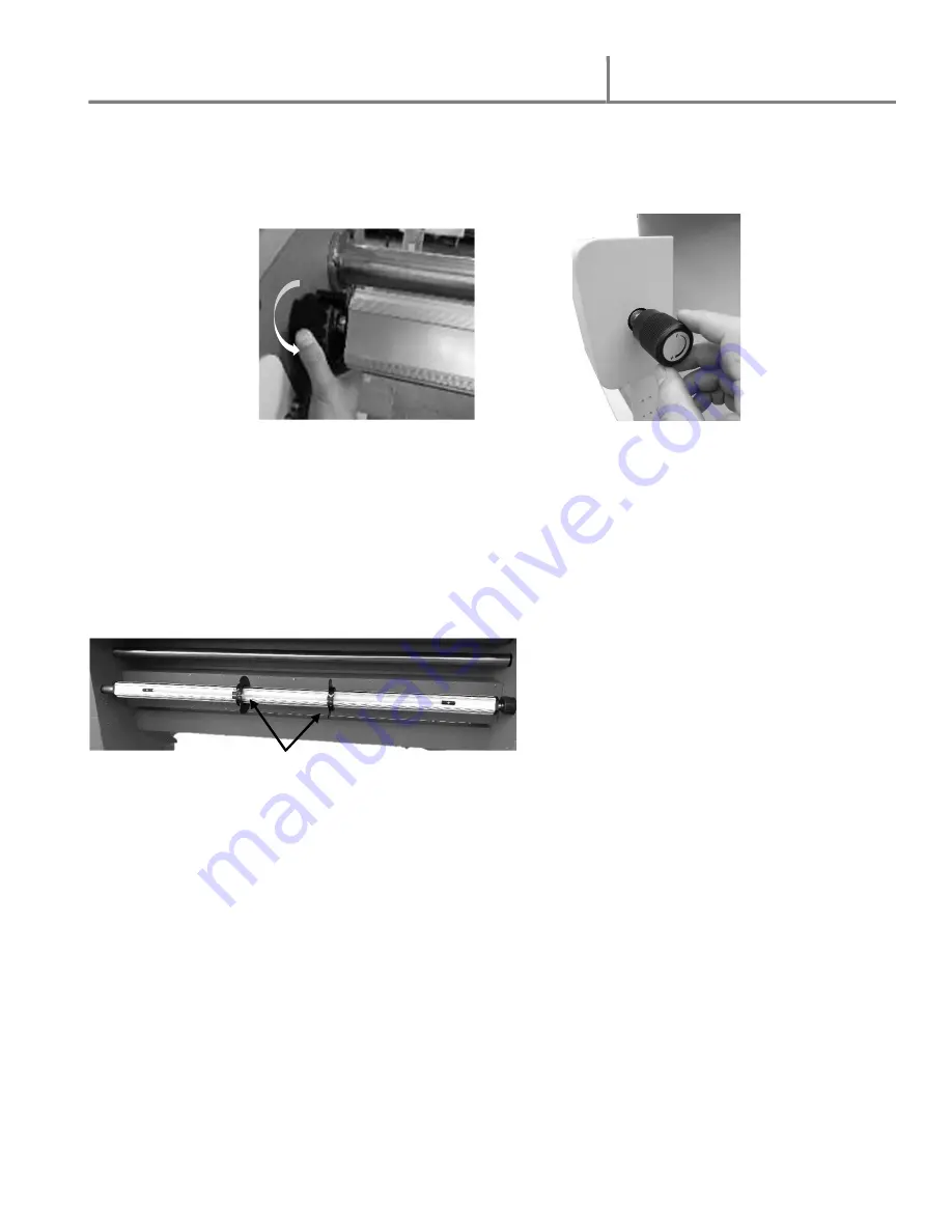
Adjust the brake tension by turning the adjusting knob on top of the supply roll assembly,
Fig 12b (see Brake tension adjustment section #15)
6.
Repeat process with bottom supply shaft using Mounting adhesive or printed media roll.
7.
Position bottom supply roll using the same number position used on the top supply roll to
align top and bottom rolls.
i.
When using printed media, position one Media Alignment Disk on each side of
the roll to keep edges lined up, Fig.12c.
ii.
Media rolls can be very slippery and ‘telescope’ when loading on the supply shaft
and running (see picture below)
14. Threading Film
1.
Pull the top film web under the rewind shaft, making sure there is proper resistance. The
resistance can be adjusted with the adjusting knob on top of the supply shaft assembly.
2.
Turn the pressure-adjusting hand-wheel to lift the top rubber roller up.
3.
Pass the film through the two rollers and lay on the rear working panel.
4.
Pull the film flat then turn the pressure-adjusting hand-wheel to lower the upper rubber
roller.
5.
Separate the paper liner from the film web to allow enough liner to be taped to the paper
rewind tube on the top rewind shaft.
NOTE: Slide film cutter between the paper liner and film to cut liner only. Be careful
not to cut the top heat roller
Bottom supply shaft with Media Alignment
Disks
NOTE:
Printed media can be very slippery
and will ‘telescope’ when loading on the
supply shaft. Use the alignment disks to keep
the edges properly lined up.
Fig. 12c Media alignment disks
Fig. 12a
Fig. 12b


