May 2011. All rights reserved. Specifications included in this manual are subject to change without prior notice .
Page
2
of
7
Installation and Operation
During installation of the modules, following guidelines should be taken into account:
Installation should be executed by qualified personnel only.
Solely use insulated and dry tools.
Ensure that any other components used in the project are compatible with the modules.
Do not apply excessive pressure or step on the modules. Be aware that sharp edged objects can
inflict permanent damage to the module.
Make sure the used support structure meets the maximal load requirements of the modules. In
regions with high possibility of snow or strong wind, always make sure that the support structure and
its mounting design are able to withstand the local environmental forces.
Do not install modules during periods of strong wind or other unusual weather conditions.
To reduce the risk of electrical shock or burns while installing the module, it is advised to cover the
module with an opaque cloth in order to keep the module in its inactive state.
Do not expose the modules to concentrated light, excessive water exposure or submerging, sources
of corrosive chemicals or salty environments.
Provide adequate ventilation to the back side of the modules to avoid heating of the module.
Insufficient ventilation may cause significant yield losses, and eventually cause permanent damage
to the module.
Always minimize shade caused by obstacles near the PV system. Shade will dramatically affect and
reduce the global PV system performance, and may eventually cause permanent damage to the
module.
When installed on a roof, the roof covering should be rated for fire-resistant capabilities. Do not install
modules on locations where flammable gas may be present at some point in time.
It is recommended to position the module in a gradient angle facing the sun in order to ensure
maximum irradiation and to avoid damage caused by flooding and other unpredictable events, such
as heavy hail impacts.
Mounting instructions
Modules can be mounted in portrait or in landscape. Use appropriate corrosion proof fastening materials.
Framed module mounting instructions
Each module must be securely fastened, using at least 4 symmetrically chosen contact points.
Modules can be mounted using mounting holes, if any, or using pressure clamps that compress the frame
from the top to the mounting rail. Four M6 (1/4”) stainless steel bolts, with nuts, washers, and lock washers
are recommended per module for long-term security.
When using pressure clamps, mount the clamps in accordance to the environmental forces the module is
exposed to. The clamping area of the washer must cover at least 130 mm². Use a torque wrench and tighten
at 20 Nm.
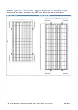
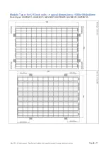
Always respect the mounting parameters and tolerances for each module type, as shown below.


