May 2011. All rights reserved. Specifications included in this manual are subject to change without prior notice .
Page
6
of
7
Frameless module mounting instructions
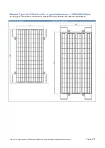
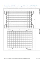
Mounting clamps or insertion rails can be used for mounting the module. When using clamps, at least 2
clamps per module side should be used. For modules with an extended width (>800mm), 3 clamps per
module side must be used. The clamp area must be at least 70mm per clamp.
Clamps or insertion rails must be equipped with rubber to protect the module against shock and dilation of
system components. Direct contact between the back side, the front side or the edge of the module and the
mounting clamps or insertion rail must be avoided at all times.
Only use mechanical fixtures for mounting the modules. Do not use adhesives or adhesive tapes for fastening
the laminates, unless they have been explicitly approved by
GH Solar
.
Please note that the module edges are particularly sensitive to impact. When mounted in harsh environment
conditions, supplementary protection on each side of the module should be provided.
Mounting the modules in excessive environmental temperatures should be avoided at all times. Dilation of all
system materials should be carefully considered prior to mounting the modules.
GH Solar
cannot be held
responsible in case of module breakage due to dilation of system components.
In case of any doubt regarding the mounting system,
GH Solar
should be contacted.
Table: module mounting instructions per module type
# of
clamps
Typical GH Solar
products
Long side mounting
and tolerance
Short side mounting and
tolerance
6x12 5inch cells
framed module
4
GH175M125,
GH180M125,
GH185M125,
GH190M125,
GH195M125,
GH200M125
(260 +/-50)mm
(180 +/-20)mm
8x12 5inch cells
framed module
4
GH235M125,
GH240M125,
GH245M125,
GH255M125,
GH260M125,
GH260M125
(310 +/-50)mm
(180 +/-20)mm
6x10 6inch cells
framed module
4
GH235P156,
GH240P156,
GH240M156,
GH250M156,
GH255M156
(310 +/-50)mm
(180 +/-20)mm
Wiring
The desired electrical output can be obtained by connecting modules in series and/or in parallel.
Make sure that the maximum system voltage is not exceeded. Limits of both junction box voltage
rating and maximal DC input voltage of the inverter (or other appliance) should be respected at all
times. Exceeding these limits will inflict irreversible damage to the whole PV system.
PV modules connected in series should have similar current. PV modules connected in parallel
should have similar voltage.
Please note that all electrical module parameters are defined under Standard Test Conditions (STC)
of 1.000 W/m² irradiance with AM 1.5 spectrum and a cell temperature of 25°C. Modules may
produce more or less voltage and/or current than reported at STC. Accordingly, the values of Isc and


