

EN
EN-5
1.1 INTRODUCTION
DANGER:
Before using the machine, carefully read the
attached “
SAFETY WARNINGS FOR THE
FLOOR SCRUBBER DRYER
” manual.
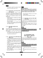
2.1 GETTING TO KNOW
THE MACHINE (Fig. 1)
1) Guide handle.
2) Control console.
3) Squeegee activation lever.
4) Water supply tap.
5) Solution tank.
6) Tank cover.
7) Clean water filling opening.
8) Wheels.
9) Removable splash guard.
10) Brush.
11) Squeegee.
12) Recovery water drain hose.
13) Squeegee water aspiration hose.
14) Recovery water tank.
15) Clean water drain/level tube.
16) Electric connection plug.
17) Clean water filter.
18) Brush up/down pedal.
19) Brush rotation activation button.
20) Touch sensor for the start-up and rota-
tion of the brush.
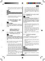
3.1 UNPACKING (Figg. 1-2)
Once the packaging has been removed as
shown in the instructions on the packaging it-
self, check that the machine and all the com-
ponents supplied are intact.
If any evident damage is found, contact the
area agent and the carrier within 3 days of
receipt.
- Remove the bag (21) containing the ac-
cessories.
- Cut the strap (22).
- Remove the wooden blocks (23 and 24).
- Lift the brush flange (9) by pressing down
on the pedal (19) (see relative para-
graph).
- Lift the wiper support (25) by lifting the
handle (3 Fig. 1) (see relative paragraph).
- Position a chute and unload the machine
from the bench.
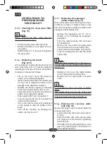
3.1.a - Standard machine equipment
(Fig. 3)
The accessories supplied are as follows:
10) Brush/brushes.
11) Wiper.
26) Water filling hose.
27) Machine use and maintenance manual.
28) Anti-tear hook.
29) Fuses.
30) Filter for clean water tank opening.
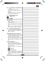
4.1 ASSEMBLING THE
COMPONENTS
4.1.a - Wiper assembly (Fig. 4)
- Loosen the two handwheels (31) located
on the wiper (11).
- Assemble the wiper (11) on the support
(25), tightening the two handwheels (31).
- Connect the tube (13) to the wiper con-
nector (32).
N.B.:
Perform the previous operations with the
wiper support lowered.
4.1.b - Brush assembly (Fig. 5)
HAZARD:
Operation to be performed by two people!
- Raise the splash guard (9) and remove
the polystyrene protection (33).
- Assemble the brush as described in the
paragraph “replacing the brush”.
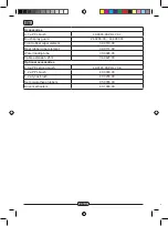
Accessories
0.7 ø PPL brush
40.0003.00 POLY 0,7
Brush spray guard
24.0265.00 + 40.4003.00
Front rubber wiper element
39.0110.00
Rear rubber wiper element
39.0111.00
Water loading tube
30.0024.00
Cable extension 25m
34.0427.00
Optional accessories
0.9 ø PPL strong brush
40.0103.00 POLY 0,9
1.2 ø PPL brush
40.0303.00
1.2 ø tynex brush
40.0203.00
Set polyurethane rubbers
95.0055.00
Drive mechanism
40.1003.00


