EN
EN-6
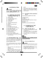
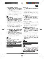
5.1 CONTROL PANEL
(Fig. 9)
20) Sensor for the start of the rotation of
the brush
Acting on the touch sensor (20) with
switch (34) “
”, the switch (38) “
” and the switch (39) “
” inserted, it
starts the rotation of the brush and the
water supply.
34) Main switch
With the plug inserted, it lights up, indicat-
ing the presence of voltage.
Pressed in “I” position, it gives the voltage
to other switches.
Pressed on “0” it stops.
35) Suction unit activation switch
The operation of the switch is enabled by
the switch (34) in position “I”.
By pressing the power switch to “I” starts
the operation of the vacuum.
37) Operating hour indicator
Indicates the machine operating hours.
38) Brush rotation enabling switch
Press the switch (38), it enables the ro-
tation of the brush; the operation of the
same is controlled by the touch sensor
(20). To disable the rotation of the brush,
press the switch (38) “
”.
39) Water solenoid valve switch
The operation of the switch is enabled by
the switch (38) in position “I”.
Press the switch (39), it prepares the
opening of the solenoid water, the ope-
ration thereof is controlled by the touch
sensor (20).
The amount of water is controlled by the
tap (4).
4) Water quantity adjustment tap
Turn the tap (4) counter-clockwise to
increase the quantity of water or turn it
clockwise to decrease it.
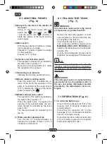
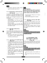
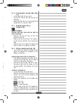
6.1 FILLING THE TANK
(Fig. 7)
WARNING:
Only add clean mains water to the tank at
a temperature no greater than 50°C.
- Remove the hose (26) supplied, connect
one end (26a) to a tap and insert the oth-
er end (26b) in the tank (5).
- Check that the tap (40) is open.
- Turn on the tap and fill the tank (5) to the
MAXIMUM LEVEL (NOT EXCEED)
indi-
cated by the label placed on the transpar-
ent tube (15).
- Pour the liquid detergent into the tank for
machines not equipped with chemical kit.
N.B.:
Use non-foamy detergents only. For the
quantities, follow the instructions provided by
the detergent manufacturer according to the
type of dirt.
DANGER:
If the detergent comes in contact with the
eyes and/or skin or if swallowed, refer to
the use and safety information booklet
provided by the manufacturer of the de-
tergent.
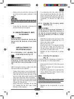
7.1 OPERATION (Fig. 8)
7.1.a - Checks before use
- Check that the exhaust tube (12) of the
recovery tank is properly coupled and
properly sealed.
- Check that the connector (41) on the
squeegee (11) is not blocked and that the
hose is connected correctly.
- Check that the clean water exhaust tube
(15) is correctly coupled to the supports
and that the tap (40) is open.
7.1.b - Electrical connection
- Introduce the cable (42) of an extension
in the tear-proff hook (28) locking it as
shown in figure.
- Connect the outlet (43) of the extension
cord (42) with the plug (16) of the ma-
chine.
- Connect the power cord to an outlet hav-
ing minimum capacity of 10A.
WARNING:
- Make sure that the mains system is
equipped with an RCD (circuit breaker).
- Unwind the electric power cable com-
pletely before operating the appliance.
- Use an electrical extension lead only
if in perfect condition; ensure that the
section is appropriate for the appliance
power rating.
- Never let the power cable run over
sharp edges and do not tread on it.
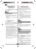
7.1.c - Preparing the machine and
choosing the cycle (Figg. 6-9)
- Press the switch (34 Fig. 6).
- Release the lever (3 Fig. 9) and lower it;
the floor squeegee (11 Fig. 9) is lowered.
- Press down on the pedal (19 Fig. 9), re-
lease it from its coupling and lift it, the
brush (10 Fig. 1) will be lowered.
NOTE:
The brush has two working positions;
Normal position “A”
It is automatically placed when you release
the pedal (19 Fig. 9) from the lifted position.
Position for persistent dirt “B”
From the “A” working position, lift the pedal
(19 Fig. 9) and engage it in the “B1” holder;
an additional pressure of 5 kg will be exer-
cised on the brush.


